Installation
Instruction manual 91/121 V6.3
9
A0V
0V analog.
10
+24V
24Vcc ±20 % – 100mA max.
11
-
Not used
12
-
Not used
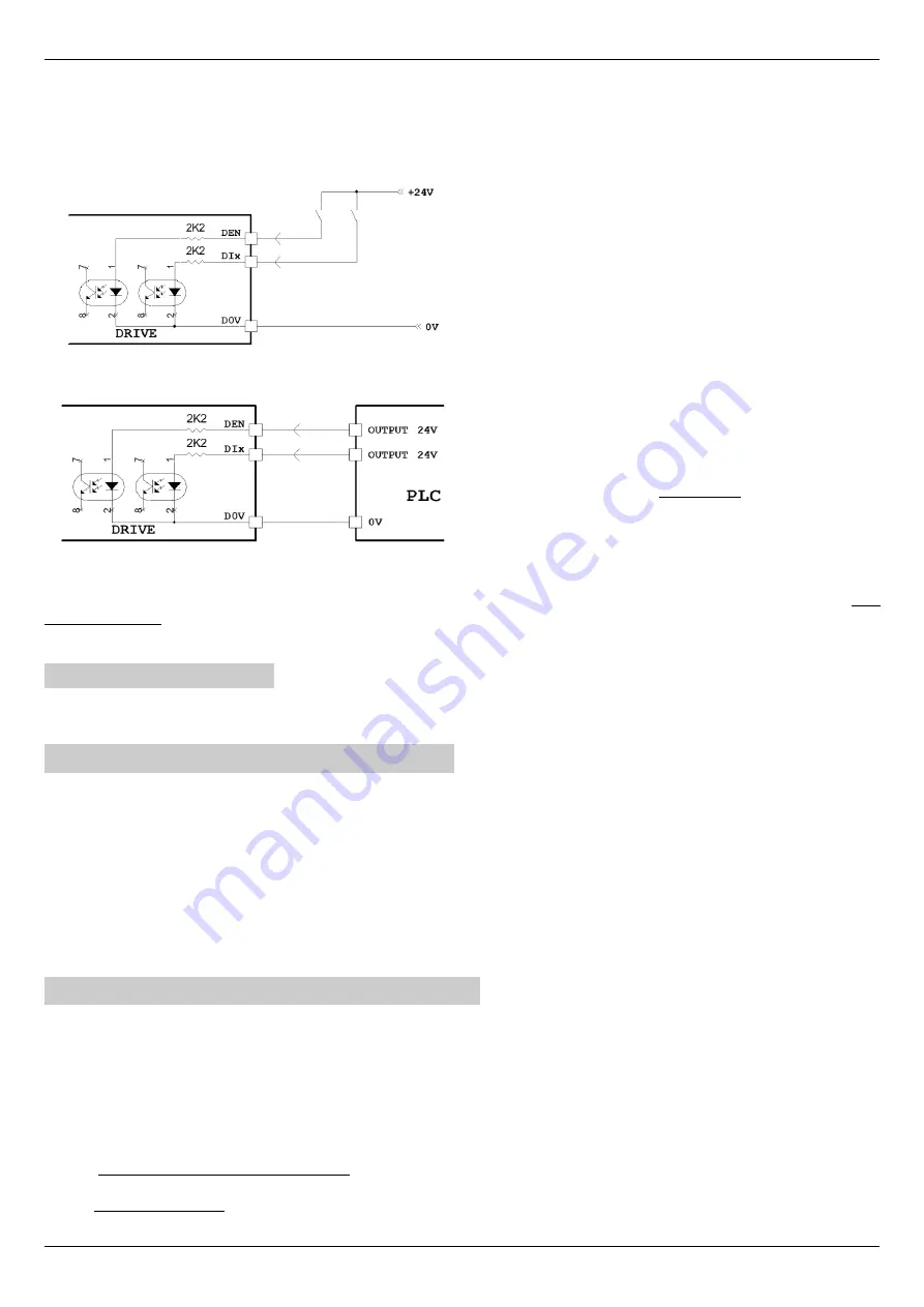
Below are some drawings to explain the correct connections to the X12 connector:
Connection of contacts to send commands to the digital inputs of
the drive.
It is necessary to connect the D0V to 0V.
Connecting a
PLC
to send commands to the digital inputs of the
drive.
The digital outputs of the PLC must provide a voltage of 24Vcc.
It is necessary to connect the 0V of the PLC with the D0V of the
drive.
The 24Vcc power supply can be supplied by the drive itself (if the total current absorbed by the loads connected to the outputs does
not exceed 100mA): connect D24 with clamp +24V (X9) and D0V with A0V clamp (X12).
If the internal power supply cannot be used, an external power supply must be used.
4.4.11 Connector X14
Transducer connection to the optional ”Transducer Board“ card. Pin assignment is variable depending on the type of card used and
therefore reference is made to the paragraph relating to the mounted board (see ”Optional transducers“ from page 55.
4.5 Commands starting sequence
Please refer to the connectors Connector X9 on page 17 and Connector X12 page 19.
1. Give 230Vca service power supply on the X10 connector.
2. When the DOK output switches to ON and the green LED DOK turns on, you can give the three-phase/mono-phase power
supply on the terminals L1, L2, L3 or C.C. power supply on the DC-BUS if this mode has been selected (see Drawing 2 on
page 12 and menu ”Power supply from“ on page 53). After the charge of the capacitors on the DC-BUS, the RDY output
switches to the ON state and the green LED RDY turns on. From this point the drive is
ready
to be enabled for operation.
3. When the RDY output switches to ON status, you can enable the drive with the DEN command.
4. When the drive is enabled and works regularly, the green RUN LED is switched on and the DOK and RDY outputs remain in
the ON state and it is possible to give the speed reference resulting in motor rotation.
4.6 Commands shutdown sequence
Please refer to the connectors Connector X9 on page 17 and Connector X12 page 19.
1. Bring the speed reference to 0V and wait for the motor to stand still. When the motor is stationary it is signalled on the selec -
ted output (normally it is the DO1 output) leading to the ON state and turning on the associated green led.
2. Deactivate the drive (DEN command = OFF). The green RUN LED goes off.
3. Remove the three-phase/mono-phase power supply (L1, L2, L3) or the D.C. power supply on the DC-BUS. The RDY output
is brought into the state of OFF, the green LED RDY turns off and the DC Bus will be discharged.
4. Remove the 230Vac service power supply (if necessary).
NOTE:
during normal motor stop-run operation
,
it is recommended to act only on the speed reference and on the enable command
(DEN) to avoid unnecessary waiting times due to the charge of capacitors on the DC-BUS. Remove line power supply only when you
want to stop the motor safely.
20
Alter Elettronica s.r.l.
Drawing 14
Drawing 13


