Installation
Instruction manual 91/121 V6.3
1
5
6
9
N. PIN SIGNAL
1
Channel “A” encoder
2
Channel ”A“ encoder
3
Channel “B” encoder
4
Channel ”B“ encoder
5
Channel “Z” encoder
6
Channel ”Z“ encoder
9
0V
View of the connector type “D” 9 poles male on the welding side.
4.4.4 Connector X6
Connection analog outputs. Voltage ±10V max or 0-10Vcc max. – Output resistance 1K
.
More information can be found in para-
graph ”Analog Output X“ on page 42.
Always use good quality shielded cables and connect the two ends of the
shield
to the ground
. On the drive case, near the connectors,
anchorages are available for screens (see Mechanical characteristics page 78).
Signal allocation to PINs:
1
A0V
0V analog. The analog 0V is connected to the drive case.
2
AO1
Analog output 1 programmable.
It is normally used to provide a voltage signal proportional to the motor torque.
3
AO2
Analog output 2 programmable.
It is normally used to provide a voltage signal proportional to the motor speed.
4
AO3
Analog output 3 programmable.
It is not normally used.
5
AO4
Analog output 4 programmable.
It is normally used to provide a voltage signal proportional to the DC BUS voltage.
6
A0V
0V analog. The analog 0V is connected to the drive case.
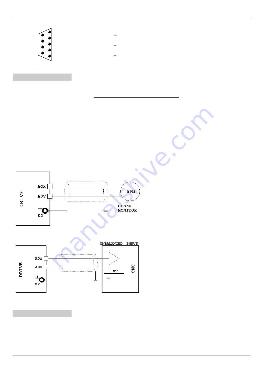
Below are some sample drawings for a correct use of the various signals on X6.
Analog output connection (±10Vcc) to a
speed indic-
ator tool.
Analog output connection (±10Vcc) to CNC
analog
input
(or a PLC) to detect motor speed.
4.4.5 Connector X7
Connector prepared for connection between two drives in "anti backlash" mode (see section ”Anti-backlash system“ from page 64).
Signal allocation to PINs:
1
T1
Resistance Bus termination value 110 Ω
.
2
T2
3
L
Connecting cable “L” pole
16
Alter Elettronica s.r.l.
Drawing 4
Drawing 5


