302
Agilent X-Series Signal Generators SCPI Command Reference
Arb Commands
Dual ARB Subsystem–N5172B/82B ([:SOURce]:RADio:ARB)
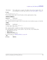
ALL
This choice enables all four markers in the waveform segment or sequence.
Example
:RAD:ARB:SEQ "SEQ:Test_Data","WFM1:ramp_test_wfm",25,M1M4,
"WFM1:sine_test_wfm",100,ALL
NOTE
A carriage return or line feed is never included in a SCPI command. The example above
contains a carriage return so that the text will fit on the page.
The preceding example creates a waveform sequence file named
Test_Data
. This file consists of the
factory–supplied waveform segments,
ramp_test_wfm
and
sine_test_wfm
. The waveform is stored in
the signal generator’s
SEQ:
directory.
•
The first segment,
ramp_test_wfm
, has 25 repetitions with markers 1 and 4 enabled.
•
The second segment,
sine_test_wfm
, has 100 repetitions with all four markers enabled.
Range
<reps>: 1 to 65535
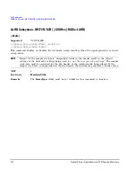
:TRIGger:TYPE
Supported
N5172B/82B
[:SOURce]:RADio:ARB:TRIGger:TYPE CONTinuous|SINGle|GATE|SADVance
[:SOURce]:RADio:ARB:TRIGger:TYPE?
This command sets the trigger mode (type) that controls the waveform’s playback.
Triggers control the playback by telling the X- Series signal generator when to play the modulating
signal (waveform). Depending on the trigger settings for the X- Series signal generator, the waveform
playback can occur once, continuously, or the X- Series signal generator may start and stop playing
the waveform repeatedly (GATE mode).
A trigger signal comprises both positive and negative signal transitions (states), which are also called
high and low periods. You can configure the X- Series signal generator to trigger on either state of the
trigger signal. It is common to have multiple triggers, also referred to as trigger occurrences or
events, occur when the signal generator requires only a single trigger. In this situation, the X- Series
signal generator recognizes the first trigger and ignores the rest.
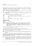
When you select a trigger mode, you may lose the signal (carrier plus modulating) from the RF
output until you trigger the waveform. This is because the X- Series signal generator sets the I and Q
signals to zero volts prior to the first trigger event, which suppresses the carrier. After the first
trigger event, the waveform’s final I and Q levels determine whether you will see the carrier signal or
not (zero = no carrier, other values = carrier visible). At the end of most files, the final I and Q
points are set to a value other than zero.
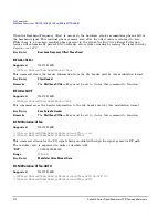
There are four parts to configuring the trigger:
•
Choosing the trigger type, which controls the waveform’s transmission.
•
Setting the waveform’s response to triggers:
Key Entry
Build New Waveform Sequence
Name and Store
Insert Waveform
Edit Repetitions
Toggle Marker 1
Toggle Marker 2
Toggle Marker 3
Toggle Marker 4
Содержание 72B
Страница 28: ...Contents Agilent X Series Signal Generators SCPI Command Reference xxviii ...
Страница 48: ...18 Agilent X Series Signal Generators SCPI Command Reference SCPI Basics SCPI Basics ...
Страница 224: ...194 Agilent X Series Signal Generators SCPI Command Reference System Commands Unit Subsystem UNIT ...
Страница 458: ...428 Agilent X Series Signal Generators SCPI Command Reference Index ...


