VistaKey Installation Guide
4–4
Mounting and Connecting Card Reader
The card reader is mounted outside the protected area in a location where a cardholder can
conveniently swipe a card past the reader. To mount and connect the card reader to
VistaKey, follow the procedure below:
Mounting the Card Reader
1. If you are installing the ADEMCO 5365BGP card reader, advance to step 2. If you are
installing a different card reader, refer to the diagram on the back of the card reader for
the color coding of the card reader wires and their function. Write down this information
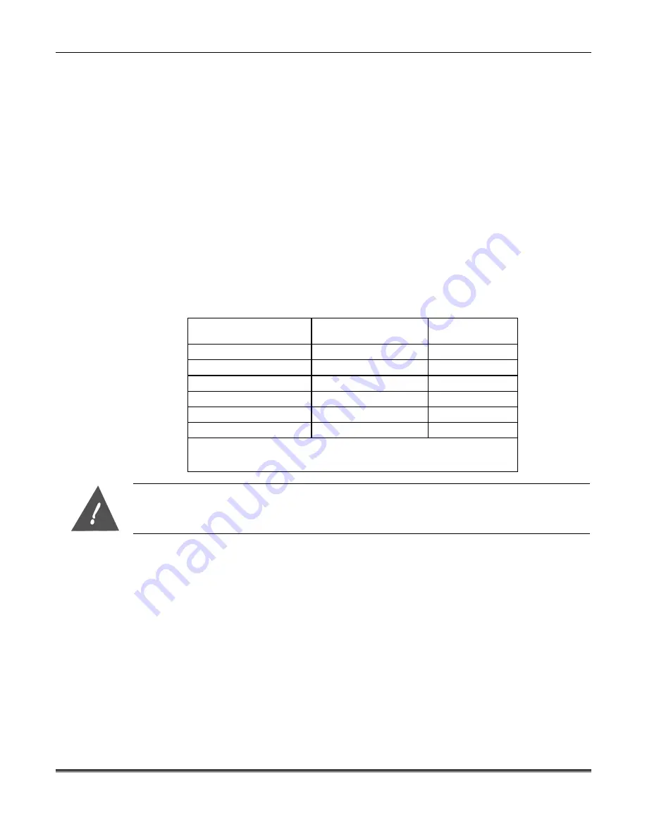
in the chart below for use in wiring the card reader to the VistaKey.
2. Using the reader as a drilling template, drill two holes in the mounting wall for the
reader.
3. Using the mounting hardware included with the reader, secure the reader to the wall.
Connecting the Card Reader
Once the card reader is mounted, you can connect it to the system. Attach the leads from the
card reader to the applicable TB3 terminals of the VistaKey as listed below and shown on the
Summary of Connections figure at the end of this manual.
Lead from
Reader
Lead
Color
To VistaKey
TB3 Terminal #
Green LED
Orange
1
Ground*
Black
2
DATA 1 (Clock)
White
3
DATA 0 (Data)
Green
4
+5VDC†
Red†
6
+12VDC†
Red†
7
* TB-3 Terminal 5 is also a ground and may be used instead of terminal 2.
Terminals 2 and 5 are a common ground.
† Connect to +5VDC OR +12VDC per reader manufacturer’s specification
The reader may have more wires than are used. The unused wires must be insulated from each
other and from any other wires or conductive material.
Connecting VistaKey Trigger
The VistaKey has one trigger output (TB3 terminal 8) that can accept a maximum current of
15mA from a source voltage of 12VDC. It is a solid-state digital switch output that may be
used to operate small loads such as LEDs and piezoelectric sounders. It can be configured as
an output committed to the access point or as an uncommitted output for general use to
control the on and off conditions of external devices.
If you are using the VistaKey trigger, connect it to the interfacing device. (Refer to the
Summary of Connections diagram at the end of this manual and the instructions provided
with the device that the trigger is being connected to.)
Connecting the VistaKey Zones
The VistaKey contains 3 zone inputs. Each zone may be configured as a supervised (tri-state)
or unsupervised (dual-state) input. Zone A is normally used to provide Door Status
Monitoring (DSM). Zone B can be configured as the Request to Exit (RTE) input. Zone C
serves as a general-purpose zone input that may be used as a tamper input.
Содержание VistaKey-SK
Страница 2: ......
Страница 6: ...vi...
Страница 8: ...viii...
Страница 40: ...VistaKey Installation Guide 4 10...
Страница 107: ......
Страница 108: ...165 Eileen Way Syosset New York 11791 Copyright 2000 PITTWAY CORPORATION l K4005 6 00...


