Chapter 3
89
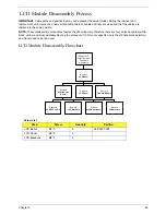
LCD Module Disassembly Process
IMPORTANT:
Cable paths and positioning may not represent the actual model. During the removal and
replacement of components, ensure all available cable channels and clips are used and that the cables are
replaced in the same position.
NOTE:
These disassembly procedures feature the 3G model only, therefore there are four antenna cables (white,
black, yellow, and blue) addressed during the procedure. If 3G is not supported, only the WLAN antennas (white
and black) need to be removed.
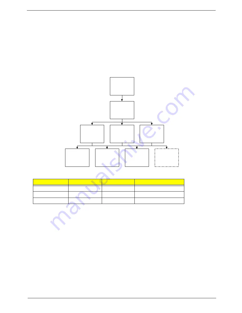
LCD Module Disassembly Flowchart
Screw List
Step
Screw
Quantity
Part No.
LCD Bezel
M2*5
6
86.S0207.002
LCD Panel
M2*3
2
LCD Brackets
M2*3
4
Remove
LCD Panel
Remove
LCD Bezel
Remove
LCD FPC Cable
Remove LCD
Panel from Main
Unit before
proceeding
Remove
LCD Brackets
Remove
WLAN Antennas
Remove
Camera Module
Remove
Microphone
Board
Remove
3G Antennas
Содержание Aspire One AO531h
Страница 6: ...VI ...
Страница 10: ...X Table of Contents ...
Страница 30: ...20 Chapter 1 ...
Страница 48: ...38 Chapter 2 ...
Страница 63: ...Chapter 3 53 8 Disconnect the FFC and remove the Keyboard ...
Страница 69: ...Chapter 3 59 4 Remove the board from the Upper Cover ...
Страница 82: ...72 Chapter 3 5 Disconnect the Bluetooth cable from the module ...
Страница 89: ...Chapter 3 79 4 Lift the CPU Fan clear of the Mainboard ...
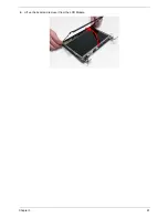
Страница 101: ...Chapter 3 91 4 Lift up the bezel and remove it from the LCD Module ...
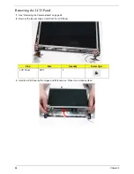
Страница 107: ...Chapter 3 97 7 Disconnect the cable from the LCD panel as shown ...
Страница 120: ...110 Chapter 3 4 Press down around the edges of the bezel to secure it in place 5 Replace the six screws and screw caps ...
Страница 138: ...128 Chapter 3 6 Insert the FFC in to the Button Board and close the locking latch ...
Страница 202: ...192 Appendix B ...
Страница 204: ...194 Appendix C ...
Страница 208: ...198 ...

