Chapter 3
133
11.
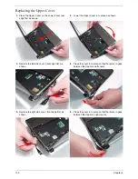
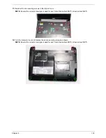
Replace the nine securing screws in the Upper Cover.
NOTE:
Ensure the correct screw type is used for each hole. Red callout: M2*5, Green callout: M2*3.
12.
Turn the computer over and replace the seven securing screws as shown.
NOTE:
Ensure the correct screw type is used for each hole. Red callout: M2*6, Green callout: M2*3.
Содержание Aspire One AO531h
Страница 6: ...VI ...
Страница 10: ...X Table of Contents ...
Страница 30: ...20 Chapter 1 ...
Страница 48: ...38 Chapter 2 ...
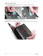
Страница 63: ...Chapter 3 53 8 Disconnect the FFC and remove the Keyboard ...
Страница 69: ...Chapter 3 59 4 Remove the board from the Upper Cover ...
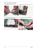
Страница 82: ...72 Chapter 3 5 Disconnect the Bluetooth cable from the module ...
Страница 89: ...Chapter 3 79 4 Lift the CPU Fan clear of the Mainboard ...
Страница 101: ...Chapter 3 91 4 Lift up the bezel and remove it from the LCD Module ...
Страница 107: ...Chapter 3 97 7 Disconnect the cable from the LCD panel as shown ...
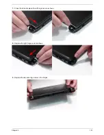
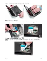
Страница 120: ...110 Chapter 3 4 Press down around the edges of the bezel to secure it in place 5 Replace the six screws and screw caps ...
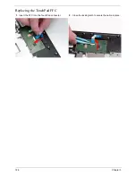
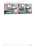
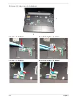
Страница 138: ...128 Chapter 3 6 Insert the FFC in to the Button Board and close the locking latch ...
Страница 202: ...192 Appendix B ...
Страница 204: ...194 Appendix C ...
Страница 208: ...198 ...

