4
Chapter 1
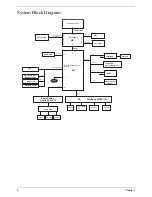
System Block Diagram
FSB
FSB
G
raphics I
n
te
rfaces
DDR SYSTEM
MEMORY
PCI-E
NB
SB
(ICH7M)
DMI
Intel Diamondville
FSB(533/667MHZ)
Channel A DDR II
Azalia
Charger
Touch Pad /B
Con.
Intel 945GMS
DMI(x2)
Intel I/O Controller Hub 7
USB 2.0 (Port0~7)
PCI-Express
DDRII-SODIMM
533 MHZ
INT_LVDS
INT_CRT
EC
4 in 1 Card Reader
LPC
K/B Con.
SPI Flash
PCIE-4
10/100 LAN
PCIE-1
PCIE-2
PCIE-3
WLAN
USB port*3
USB-1,2,4
SATA
IHDA
LPC
RTC
BATTERY
USB
DMI
Audio Jack
Int. SPK
Int. MIC
Audio Codec
SATA 0
SATA - HDD
SD Cardreader
USB-0
USB-7
Audio AMP
3G/WiMAX
USB-6
USB-5
SIM Card
CRT
10.1"Panel
Realtek ALC272
CCD
Bluetooth module
Realtek RTS5159
Atheros 8132/8114
JM385
Winbond WPCE775L
USB-3
Содержание Aspire One AO531h
Страница 6: ...VI ...
Страница 10: ...X Table of Contents ...
Страница 30: ...20 Chapter 1 ...
Страница 48: ...38 Chapter 2 ...
Страница 63: ...Chapter 3 53 8 Disconnect the FFC and remove the Keyboard ...
Страница 69: ...Chapter 3 59 4 Remove the board from the Upper Cover ...
Страница 82: ...72 Chapter 3 5 Disconnect the Bluetooth cable from the module ...
Страница 89: ...Chapter 3 79 4 Lift the CPU Fan clear of the Mainboard ...
Страница 101: ...Chapter 3 91 4 Lift up the bezel and remove it from the LCD Module ...
Страница 107: ...Chapter 3 97 7 Disconnect the cable from the LCD panel as shown ...
Страница 120: ...110 Chapter 3 4 Press down around the edges of the bezel to secure it in place 5 Replace the six screws and screw caps ...
Страница 138: ...128 Chapter 3 6 Insert the FFC in to the Button Board and close the locking latch ...
Страница 202: ...192 Appendix B ...
Страница 204: ...194 Appendix C ...
Страница 208: ...198 ...


