Chapter 1
15
Hardware Specifications and Configurations
Processor
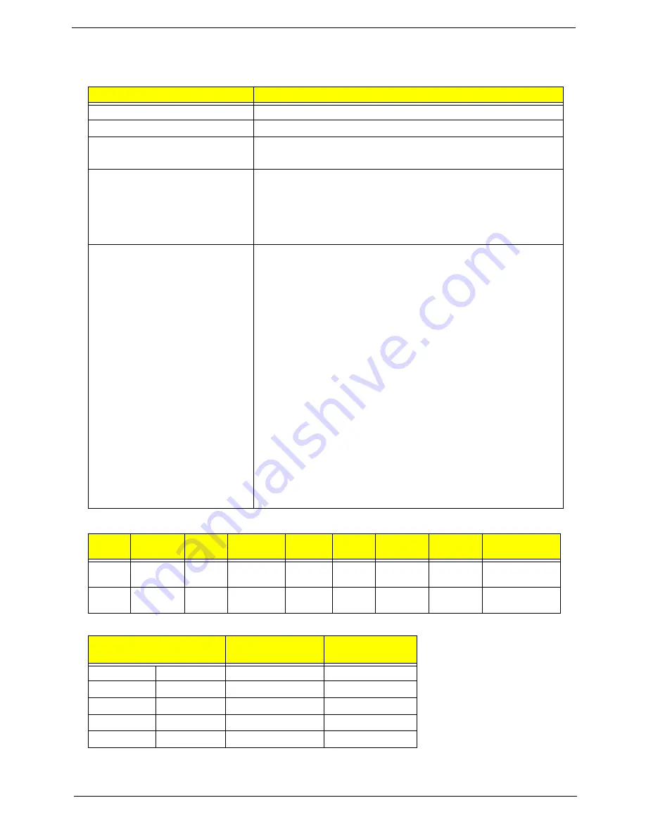
Processor Specifications
CPU Fan Tru Value Table
•
Throttling 50%: On= 84°C; OFF=86°C
•
OS shut down at 88°C; H/W shut down(PH1) at 95°C
Item
Specification
CPU type
Intel Atom N270 1.6G 512K 533 2.5W
CPU package
Micro-FCBGA8 packaging, 437-pin
Core Logic
•
Intel 945GMS
•
ICH7M
Chipset
•
ENE KB926 for Keyboard Controller, Battery management
Unit, and RTC.
•
Integrated VGA solution for Intel 945GSE.
•
Realtek ALC272X-GR for High Definition Audio Codec.
•
Atheros AR8114A for 10/100 LAN
Features
•
On-die, primary 32-kB instructions cache and 24-kB write-back
data cache
•
533-MHz source-synchronous front side bus (FSB)
•
2-Threads support
•
On-die 512-kB, 8-way L2 cache
•
Support for IA 32-bit architecture
•
Intel® Streaming SIMD Extensions-2 and -3 (Intel® SSE2 and
Intel® SSE3) support and Supplemental Streaming SIMD
Extension 3 (SSSE3) support
•
Micro-FCBGA8 packaging technologies
•
Thermal management support via Intel® Thermal Monitor 1
and Intel Thermal Monitor 2
•
FSB Lane Reversal for flexible routing
•
Supports C0/C1(e)/C2(e)/C4(e)
•
L2 Dynamic Cache Sizing
•
Advanced power management features including Enhanced
Intel SpeedStep® Technology
•
Execute Disable Bit support for enhanced security
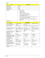
Item
CPU
Speed
Cores
Bus
Speed
Mfg
Tech
Cache
Size
Package
Core
Voltage
Acer P/N
N270
1.6 GHz
1
533 MHz
45 nm
512
KB
Micro-
FCBGA8
KC.ANB01.270
N280
1.66 GHz
1
667 MHz
45 nm
512
KB
Micro-
FCBGA8
KC.ANB01.280
CPU Temperature of
Diode
Fan Speed (RPM)
SPL Spec (dBA)
40
44
3300
26
50
54
3800
29
60
63
4300
31
68
73
5500
35
76
82
90% Duty
Содержание Aspire One AO531h
Страница 6: ...VI ...
Страница 10: ...X Table of Contents ...
Страница 30: ...20 Chapter 1 ...
Страница 48: ...38 Chapter 2 ...
Страница 63: ...Chapter 3 53 8 Disconnect the FFC and remove the Keyboard ...
Страница 69: ...Chapter 3 59 4 Remove the board from the Upper Cover ...
Страница 82: ...72 Chapter 3 5 Disconnect the Bluetooth cable from the module ...
Страница 89: ...Chapter 3 79 4 Lift the CPU Fan clear of the Mainboard ...
Страница 101: ...Chapter 3 91 4 Lift up the bezel and remove it from the LCD Module ...
Страница 107: ...Chapter 3 97 7 Disconnect the cable from the LCD panel as shown ...
Страница 120: ...110 Chapter 3 4 Press down around the edges of the bezel to secure it in place 5 Replace the six screws and screw caps ...
Страница 138: ...128 Chapter 3 6 Insert the FFC in to the Button Board and close the locking latch ...
Страница 202: ...192 Appendix B ...
Страница 204: ...194 Appendix C ...
Страница 208: ...198 ...

