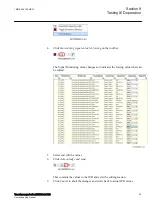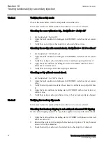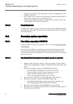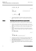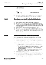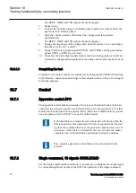
Check, in the same way, the operate and reset values of
IBase1
for phases L2 and
L3.
5.
Activate the cooling input signal, thus switching to base current
IBase2
.
6.
Check the operate and reset values (for all three phases) for
IBase2
in the same
way as described above for stage
IBase1
.
7.
Deactivate the input signal for stage
IBase2
.
8.
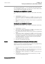
Set the time constant for
IBase1
in accordance with the setting plan.
9.
Set the injection current for phase L1 to 1.50 ·
IBase1
.
10. Connect a trip output contact to the timer and monitor the output of contacts
ALARM1 and ALARM2 to digital inputs in test equipment.
Read the heat content in the thermal protection from the local HMI and wait until
the content is zero.
11. Switch on the injection current and check that ALARM1 and ALARM2 contacts
operate at the set percentage level and that the operate time for tripping is in
accordance with the set Time Constant 1 (
Tau1
).
With setting Itr = 101%
IBase1
and injection current 1.50 ·
IBase1
, the trip time
from zero content in the memory shall be 0.60 · Time Constant 1 (
Tau1
).
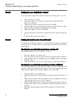
12. Check that all trip and alarm contacts operate according to the configuration
logic.
13. Switch off the injection current and check from the service menu readings of
thermal status and LOCKOUT that the lockout resets at the set percentage of
heat content.
14. Activate the cooling input signal to switch over to base current
IBase2
.
Wait 5 minutes to empty the thermal memory and set Time Constant 2 (
Tau2
) in
accordance with the setting plan.
15. Test with injection current 1.50 ·
IBase2
the thermal alarm level, the operate
time for tripping and the lockout reset in the same way as described for stage
IBase1
.
16. Finally check that start and trip information is stored in the event menu.
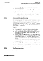
10.4.5.2
Completing the test
Continue to test another function or end the test by changing the
TESTMODE
setting
to
Off
. Restore connections and settings to their original values, if they were changed
for testing purposes.
10.4.6
Breaker failure protection, phase segregated activation and
output CCRBRF
Prepare the IED for verification of settings outlined in section
The Breaker failure protection, 3-phase activation and output function CCRBRF
should normally be tested in conjunction with some other function that provides a start
signal. An external START signal can also be used.
To verify the settings in the most common back-up trip mode
1 out of 3
, it is sufficient
to test phase-to-earth faults.
Section 10
1MRK 504 160-UEN -
Testing functionality by secondary injection
76
Transformer protection RET650 2.1 IEC
Commissioning manual
Содержание RET650 2.1 IEC
Страница 1: ...Relion 650 series Transformer protection RET650 2 1 IEC Commissioning manual ...
Страница 2: ......
Страница 24: ...18 ...
Страница 32: ...26 ...
Страница 48: ...42 ...
Страница 52: ...46 ...
Страница 72: ...66 ...
Страница 110: ...104 ...
Страница 116: ...110 ...
Страница 125: ...119 ...


