


0
L1
L2
L3
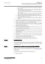
3
=
I
I
I
I
×
+
+
IECEQUATION00019 V1 EN
(Equation 4)
Where:
1
2
3
L
L
L
I
I and I
,
IECEQUATION00020 V1 EN
are the measured phase currents
7.
Compare the result with the set value of the zero-sequence operate current.
Consider that the set value
3I0<
is in percentage of the base current
IBase
.
10.6.1.4
Measuring the operate value for the dead line detection function
1.
Apply three-phase voltages with their rated value and zero currents.
2.
Decrease the measured voltage in one phase until the DLD1PH signal appears.
3.
This is the point at which the dead line condition is detected. Check the value of
the decreased voltage with the set value UDLD< (UDLD< is in percentage of the
base voltage
UBase
).
4.
Apply three-phase currents with their rated value and zero voltages.
5.
Decrease the measured current in one phase until the DLD1PH signal appears.
6.
This is the point at which the dead line condition is detected. Check the value of
the decreased current with the set value IDLD< (IDLD< is in percentage of the
base current
IBase
).
10.6.1.5
Checking the operation of the du/dt and di/dt based function
Check the operation of the du/dt and di/dt based function if included in the IED.
1.
Simulate normal operating conditions with the three-phase currents in phase
with their corresponding phase voltages and with all of them equal to their rated
values.
2.
Change the voltages and currents in all three phases simultaneously.
The voltage change must be higher than the set value
DU>
and the current
change must be lower than the set value
DI<
.
•
The BLKU and BLKZ signals appear without any time delay. The BLKZ
signal will be activated only if the internal deadline detection is not
activated at the same time.
•
3PH should appear after 5 seconds, if the remaining voltage levels are
lower than the set
UDLD<
of the dead line detection function.
3.
Apply normal conditions as in step
.
The BLKU, BLKZ and 3PH signals should reset, if activated, see step
and
.
4.
Change the voltages and currents in all three phases simultaneously.
The voltage change must be higher than the set value
DU>
and the current
change must be higher than the set value
DI<
.
1MRK 504 160-UEN -
Section 10
Testing functionality by secondary injection
Transformer protection RET650 2.1 IEC
87
Commissioning manual
Содержание RET650 2.1 IEC
Страница 1: ...Relion 650 series Transformer protection RET650 2 1 IEC Commissioning manual ...
Страница 2: ......
Страница 24: ...18 ...
Страница 32: ...26 ...
Страница 48: ...42 ...
Страница 52: ...46 ...
Страница 72: ...66 ...
Страница 110: ...104 ...
Страница 116: ...110 ...
Страница 125: ...119 ...


