285
Binary signal transfer to remote end
(RTC)
&KDSWHU
/RJLF
%LQDU\VLJQDOWUDQVIHUWRUHPRWHHQG57&
$SSOLFDWLRQ
The binary signal transfer function is preferably used for sending communication
scheme related signals, transfer trip and/or other binary signals required at the remote
end. Up to 32 selectable binary send signals, internal or external, and 32 selectable bi-
nary receive signals can be transmitted.
Together with the binary signals internal to the terminal, the function is utilising binary
inputs and outputs. The function can be provided with various 56/64 kbit/s communi-
cation modules for optical fibre or galvanic connection.
The communication can be done via direct galvanic communication line for shorter dis-
tances, via dedicated optical fibres up to around 30 km and via a communication net-
work for longer distances.
'HVLJQ
The function Binary signal transfer to remote end consists of two function blocks,
RTC1 and RTC2, each handling 16 inputs (SEND01-16) and 16 outputs (REC01-16).
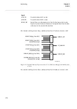
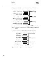
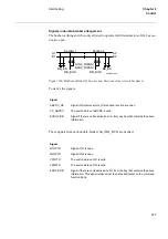
Figure 161 shows the signal diagram for RTC1. This diagram is also valid for RTC2
since the signal inputs and outputs are the same.
A signal applied to an input of one function block, e.g. RTC1-SEND01, in one terminal
will be transmitted, via a data communication link, to a remote terminal and there ap-
pear at the corresponding output of the corresponding function block, that is in the ex-
ample RTC1-REC01. The transmission takes 10 - 25 ms plus communication link
delay. No additional security actions to that included in the communication handling,
that is CRC-check, checking length of telegram and addressing, are incorporated.
Both function blocks have an input BLOCK, which is available to block the operation.
When the input is energized, all 16 binary input signals of that function block will be
sent as zeroes. Incoming signals from remote end are not affected.
An output COMFAIL is also available to announce an alarm when there is a failure in
the communication with the remote terminal. The COMFAIL for both function blocks
works in parallel so information will appear simultaneously on both function blocks. At
COMFAIL all 16 output signal on both function blocks will be set to zero.
Содержание REO 517
Страница 10: ... RQWHQWV ...
Страница 16: ...6 Introduction to the application manual KDSWHU QWURGXFWLRQ ...
Страница 64: ...54 Blocking of signals during test KDSWHU RPPRQ IXQFWLRQV ...
Страница 88: ...78 Scheme communication logic ZCOM KDSWHU LQH LPSHGDQFH ...
Страница 100: ...90 Time delayed phase and residual overcurrent protection TOC1 KDSWHU XUUHQW Equation 36 Iset IsSEC I1b 100 ...
Страница 146: ...136 Unbalance protection for capacitor banks TOCC KDSWHU XUUHQW ...
Страница 166: ...156 Dead line detection DLD KDSWHU 3RZHU V VWHP VXSHUYLVLRQ ...
Страница 171: ...161 About this chapter KDSWHU RQWURO KDSWHU RQWURO ERXW WKLV FKDSWHU This chapter describes the control functions ...
Страница 293: ...283 About this chapter KDSWHU RJLF KDSWHU RJLF ERXW WKLV FKDSWHU This chapter describes the logic functions ...
Страница 378: ...368 Monitoring of DC analog measurements KDSWHU 0RQLWRULQJ ...
Страница 379: ...369 About this chapter KDSWHU 0HWHULQJ KDSWHU 0HWHULQJ ERXW WKLV FKDSWHU This chapter describes the metering functions ...
Страница 384: ...374 Pulse counter logic PC KDSWHU 0HWHULQJ ...
Страница 412: ...402 Serial communication modules SCM KDSWHU DWD FRPPXQLFDWLRQ ...
Страница 440: ...430 LED indication module KDSWHU DUGZDUH PRGXOHV ...


