43
Logic function blocks
&KDSWHU
&RPPRQIXQFWLRQV
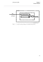
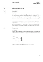
)LJXUH )XQFWLRQEORFNGLDJUDPRIWKH;25IXQFWLRQ
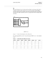
The output signal (OUT) is set to 1 if the input signals are different and to 0 if they are
equal. See truth table below.
7DEOH
7UXWKWDEOHIRUWKH;25IXQFWLRQEORFN
6HW5HVHW65
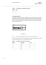
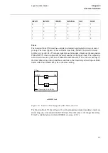
The function block Set-Reset (SR) (figure 21) has two inputs, designated SRnn-SET
and SRnn-RESET, where nn presents the serial number of the block. Each SR circuit
has two outputs, SRnn-OUT and SRnn-NOUT (inverted). The output (OUT) is set to 1
if the input (SET) is set to 1 and if the input (RESET) is 0. If the reset input is set to 1,
the output is unconditionally reset to 0.
,1387 ,1387
287
1287
0
0
0
1
0
1
1
0
1
0
1
0
1
1
0
1
=1
OUT
1
NOUT
INPUT1
INPUT2
XOnn
xx00000517.vsd
Содержание REO 517
Страница 10: ... RQWHQWV ...
Страница 16: ...6 Introduction to the application manual KDSWHU QWURGXFWLRQ ...
Страница 64: ...54 Blocking of signals during test KDSWHU RPPRQ IXQFWLRQV ...
Страница 88: ...78 Scheme communication logic ZCOM KDSWHU LQH LPSHGDQFH ...
Страница 100: ...90 Time delayed phase and residual overcurrent protection TOC1 KDSWHU XUUHQW Equation 36 Iset IsSEC I1b 100 ...
Страница 146: ...136 Unbalance protection for capacitor banks TOCC KDSWHU XUUHQW ...
Страница 166: ...156 Dead line detection DLD KDSWHU 3RZHU V VWHP VXSHUYLVLRQ ...
Страница 171: ...161 About this chapter KDSWHU RQWURO KDSWHU RQWURO ERXW WKLV FKDSWHU This chapter describes the control functions ...
Страница 293: ...283 About this chapter KDSWHU RJLF KDSWHU RJLF ERXW WKLV FKDSWHU This chapter describes the logic functions ...
Страница 378: ...368 Monitoring of DC analog measurements KDSWHU 0RQLWRULQJ ...
Страница 379: ...369 About this chapter KDSWHU 0HWHULQJ KDSWHU 0HWHULQJ ERXW WKLV FKDSWHU This chapter describes the metering functions ...
Страница 384: ...374 Pulse counter logic PC KDSWHU 0HWHULQJ ...
Страница 412: ...402 Serial communication modules SCM KDSWHU DWD FRPPXQLFDWLRQ ...
Страница 440: ...430 LED indication module KDSWHU DUGZDUH PRGXOHV ...

