24
Time synchronisation (TIME)
&KDSWHU
&RPPRQIXQFWLRQV
7LPHV\QFKURQLVDWLRQ7,0(
$SSOLFDWLRQ
Use time synchronisation to achieve a common time base for the terminals in a protec-
tion and control system. This makes comparision of events and disturbance data be-
tween all terminals in the system possible.
Time-tagging of internal events and disturbances is an excellent help when evaluating
faults. Without time synchronisation, only the events within the terminal can be com-
pared to one another. With time synchronisation, events and disturbances within the en-
tire station, and even between line ends, can be compared during an evaluation.
)XQFWLRQDOLW\
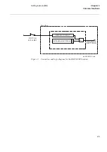
Two main alternatives of external time synchronisation are available. Either the syn-
chronisation message is applied via any of the communication ports of the terminal as
a telegram message including date and time, or as a minute pulse, connected to a binary
input. The minute pulse is used to fine tune already existing time in the terminals.
The REx 5xx terminal has its own internal clock with date, hour, minute, second and
millisecond. It has a resolution of 1 ms.
The clock has a built-in calendar that handles leap years through 2098. Any change be-
tween summer and winter time must be handled manually or through external time syn-
chronisation. The clock is powered by a capacitor, to bridge interruptions in power
supply without malfunction.
The internal clock is used for time-tagging disturbances, events in Substation monitor-
ing system (SMS) and Substation control system (SCS), and internal events.
&DOFXODWLRQV
The time is set with year, month, day and time. Refer to the
,QVWDOODWLRQDQGFRPPLV
VLRQLQJPDQXDO
for information on the setting procedure.
When the source of time synchronization is selected on the local HMI, the parameter is
called TimeSyncSource. The time synchronisation source can also be set from the CAP
tool. The setting parameter is then called SYNCSCR. The setting alternatives are:
•
None (no synchronisation)
•
LON
•
SPA
Содержание REO 517
Страница 10: ... RQWHQWV ...
Страница 16: ...6 Introduction to the application manual KDSWHU QWURGXFWLRQ ...
Страница 64: ...54 Blocking of signals during test KDSWHU RPPRQ IXQFWLRQV ...
Страница 88: ...78 Scheme communication logic ZCOM KDSWHU LQH LPSHGDQFH ...
Страница 100: ...90 Time delayed phase and residual overcurrent protection TOC1 KDSWHU XUUHQW Equation 36 Iset IsSEC I1b 100 ...
Страница 146: ...136 Unbalance protection for capacitor banks TOCC KDSWHU XUUHQW ...
Страница 166: ...156 Dead line detection DLD KDSWHU 3RZHU V VWHP VXSHUYLVLRQ ...
Страница 171: ...161 About this chapter KDSWHU RQWURO KDSWHU RQWURO ERXW WKLV FKDSWHU This chapter describes the control functions ...
Страница 293: ...283 About this chapter KDSWHU RJLF KDSWHU RJLF ERXW WKLV FKDSWHU This chapter describes the logic functions ...
Страница 378: ...368 Monitoring of DC analog measurements KDSWHU 0RQLWRULQJ ...
Страница 379: ...369 About this chapter KDSWHU 0HWHULQJ KDSWHU 0HWHULQJ ERXW WKLV FKDSWHU This chapter describes the metering functions ...
Страница 384: ...374 Pulse counter logic PC KDSWHU 0HWHULQJ ...
Страница 412: ...402 Serial communication modules SCM KDSWHU DWD FRPPXQLFDWLRQ ...
Страница 440: ...430 LED indication module KDSWHU DUGZDUH PRGXOHV ...


