13
Requirements
&KDSWHU
*HQHUDO
All testing was made without any remanence flux in the current transformer core. The
requirements below are therefore fully valid for a core with no remanence flux. It is dif-
ficult to give general recommendations for additional margins for remanence flux. They
depend on the reliability and economy requirements.
When current transformers of low remanence type (TPY) are used, practically no addi-
tional margin is needed.
For current transformers of high remanence type (e.g. TPX), the small probability of a
fully asymmetrical fault, together with maximum remanence flux in the same direction
as the flux generated by the fault, has to be kept in mind at the decision of an additional
margin. Fully asymmetrical fault current will be achieved when the fault occurs at zero
voltage (0°). Investigations have proved that 95% of the faults in the network will occur
when the voltage is between 40° and 90°.
)DXOWFXUUHQW
The current transformer requirements are based on the maximum fault current for faults
in different positions. Maximum fault current will occur for three-phase faults or single-
phase-to-earth faults. The current for a single phase-to-earth fault will exceed the cur-
rent for a three-phase fault when the zero sequence impedance in the total fault loop is
less than the positive sequence impedance.
When calculating the current transformer requirements, maximum fault current should
be used and therefore both fault types have to be considered.
&DEOHUHVLVWDQFHDQGDGGLWLRQDOORDG
The current transformer saturation is directly affected by the voltage at the current
transformer secondary terminals. This voltage, for an earth fault, is developed in a loop
containing the phase and neutral conductor, and relay load. For three-phase faults, the
neutral current is zero, and only the phase conductor and relay phase load have to be
considered.
In the calculation, the loop resistance should be used for phase-to-earth faults and the
phase resistance for three-phase faults.
&XUUHQWWUDQVIRUPHUUHTXLUHPHQWVIRU&7VDFFRUGLQJWRWKH,(& VWDQGDUG
The current transformer ratio should be selected so that the current to the protection is
higher than the minimum operating value for all faults that are to be detected. The min-
imum operating current is 10-30% of the nominal current.
All current transformers of high remanence and low remanence type that fulfil the re-
quirements on the rated equivalent secondary e.m.f. E
al
below can be used. The current
transformers should have an accuracy class comparable to 5P or better. The character-
Содержание REO 517
Страница 10: ... RQWHQWV ...
Страница 16: ...6 Introduction to the application manual KDSWHU QWURGXFWLRQ ...
Страница 64: ...54 Blocking of signals during test KDSWHU RPPRQ IXQFWLRQV ...
Страница 88: ...78 Scheme communication logic ZCOM KDSWHU LQH LPSHGDQFH ...
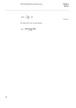
Страница 100: ...90 Time delayed phase and residual overcurrent protection TOC1 KDSWHU XUUHQW Equation 36 Iset IsSEC I1b 100 ...
Страница 146: ...136 Unbalance protection for capacitor banks TOCC KDSWHU XUUHQW ...
Страница 166: ...156 Dead line detection DLD KDSWHU 3RZHU V VWHP VXSHUYLVLRQ ...
Страница 171: ...161 About this chapter KDSWHU RQWURO KDSWHU RQWURO ERXW WKLV FKDSWHU This chapter describes the control functions ...
Страница 293: ...283 About this chapter KDSWHU RJLF KDSWHU RJLF ERXW WKLV FKDSWHU This chapter describes the logic functions ...
Страница 378: ...368 Monitoring of DC analog measurements KDSWHU 0RQLWRULQJ ...
Страница 379: ...369 About this chapter KDSWHU 0HWHULQJ KDSWHU 0HWHULQJ ERXW WKLV FKDSWHU This chapter describes the metering functions ...
Страница 384: ...374 Pulse counter logic PC KDSWHU 0HWHULQJ ...
Страница 412: ...402 Serial communication modules SCM KDSWHU DWD FRPPXQLFDWLRQ ...
Страница 440: ...430 LED indication module KDSWHU DUGZDUH PRGXOHV ...


