


30
I/O system configurator (IOP)
&KDSWHU
&RPPRQIXQFWLRQV
,2V\VWHPFRQILJXUDWRU,23
$SSOLFDWLRQ
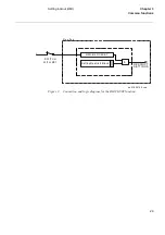
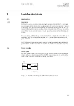
The I/O system configurator must be used in order to recognize included modules and
to create internal adress mappings between modules and protections and other func-
tions.
)XQFWLRQDOLW\
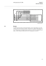
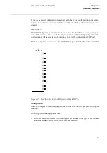
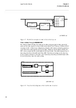
The I/O system configurator is used to add, remove or move I/O modules in the REx
5xx terminals. To configure means to connect the function blocks that represent each I/
O module (BIM, BOM, IOM,IOPSM, DCM and MIM) to a function block for the I/O
positions (IOP1) that represent the physical slot in the rack.
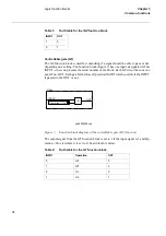
Available I/O modules are:
•
BIM,
%
inary
,
nput
0
odule with 16 binary input channels.
•
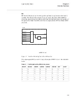
BOM,
%
inary
2
utput
0
odule with 24 binary output channels.
•
IOM,
,
nput/
2
utput
0
odule with 8 binary input and 12 binary output channels.
•
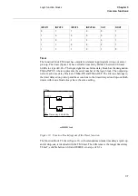
MIM,
P
A
,
nput
0
odule with six analog input channels.
•
IOPSM,
,
nput
2
utput
3RZHU6
upply
0
odule with four inputs and four outputs.
•
DCM,
'
ata
&
ommunication
0
odule. The only software configuration for this mod-
ule is the I/O Position input.
An REx 5xx terminal houses different numbers of modules depending which kind of
modules chosen.
It is possible to fit modules of different types in any combination in a terminal, but the
total maximum numbers of modules must be considered. The maximum number of mA
Input modules are also limited.
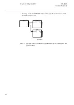
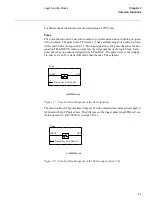
Each I/O-module can be placed in any CAN-I/O slot in the casing with one exception.
The DCM-module has a fixed slot position that depends on the size of the casing.
To add, remove or move modules in the terminal, the reconfiguration of the terminal
must be done from the graphical configuration CAP tool.
Users refer to the CAN-I/O slots by the physical slot numbers, which also appear in the
terminal drawings.
Содержание REO 517
Страница 10: ... RQWHQWV ...
Страница 16: ...6 Introduction to the application manual KDSWHU QWURGXFWLRQ ...
Страница 64: ...54 Blocking of signals during test KDSWHU RPPRQ IXQFWLRQV ...
Страница 88: ...78 Scheme communication logic ZCOM KDSWHU LQH LPSHGDQFH ...
Страница 100: ...90 Time delayed phase and residual overcurrent protection TOC1 KDSWHU XUUHQW Equation 36 Iset IsSEC I1b 100 ...
Страница 146: ...136 Unbalance protection for capacitor banks TOCC KDSWHU XUUHQW ...
Страница 166: ...156 Dead line detection DLD KDSWHU 3RZHU V VWHP VXSHUYLVLRQ ...
Страница 171: ...161 About this chapter KDSWHU RQWURO KDSWHU RQWURO ERXW WKLV FKDSWHU This chapter describes the control functions ...
Страница 293: ...283 About this chapter KDSWHU RJLF KDSWHU RJLF ERXW WKLV FKDSWHU This chapter describes the logic functions ...
Страница 378: ...368 Monitoring of DC analog measurements KDSWHU 0RQLWRULQJ ...
Страница 379: ...369 About this chapter KDSWHU 0HWHULQJ KDSWHU 0HWHULQJ ERXW WKLV FKDSWHU This chapter describes the metering functions ...
Страница 384: ...374 Pulse counter logic PC KDSWHU 0HWHULQJ ...
Страница 412: ...402 Serial communication modules SCM KDSWHU DWD FRPPXQLFDWLRQ ...
Страница 440: ...430 LED indication module KDSWHU DUGZDUH PRGXOHV ...


