


160
Fuse failure supervision (FFRW)
&KDSWHU
6HFRQGDU\V\VWHPVXSHUYLVLRQ
internal functions of the terminal itself in order to receive a block command from inter-
nal functions. Through OR gate it can be connected to both binary inputs and internal
function outputs.
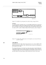
Function input signal FFRW-MCB is to be connected via a terminal binary input to the
N.C. auxiliary contact of the miniature circuit breaker protecting the VT secondary cir-
cuit.
Function input signal FFRW-DISC is to be connected via a terminal binary input to the
N.C. auxiliary contact of the line disconnector.
The function output FFRW-VTSU can be used for blocking the voltage related measur-
ing functions (undervoltage protection, synchrocheck etc.) except for the impedance
protection.
Function output FFRW-VTSZ can be used for blocking the impedance protection func-
tion.
The FFRW-MCB signal sets the output signals FFRW-VTSU and FFRW-VTSZ in or-
der to block all the voltage related functions when the MCB is open. The additional
drop-off timer of 150 ms prolongs the presence of FFRW-MCB signal to prevent the
unwanted operation of voltage dependent function due to non simultaneous closing of
the main contacts of the miniature circuit breaker.
The FFRW-DISC signal sets the output signal FFRW-VTSU in order to block the volt-
age related functions when the line disconnector is open. The impedance protection
function is not affected by the position of the line disconnector.
If a fuse failure condition is detected, the signal FFRW-VTSU is turned high, and
FFRW-VTSZ is high.
&DOFXODWLRQV
The parameters for the fuse failure supervision function are set via the local HMI or
PST (Parameter Setting Tool). Refer to the Technical reference manual for setting pa-
rameters and path in local HMI.
The minimum operate values for the operation of the current and voltage measuring el-
ements must always be set with a safety margin of 10-15%, depending on the operating
conditions of the power system.
Содержание REO 517
Страница 10: ... RQWHQWV ...
Страница 16: ...6 Introduction to the application manual KDSWHU QWURGXFWLRQ ...
Страница 64: ...54 Blocking of signals during test KDSWHU RPPRQ IXQFWLRQV ...
Страница 88: ...78 Scheme communication logic ZCOM KDSWHU LQH LPSHGDQFH ...
Страница 100: ...90 Time delayed phase and residual overcurrent protection TOC1 KDSWHU XUUHQW Equation 36 Iset IsSEC I1b 100 ...
Страница 146: ...136 Unbalance protection for capacitor banks TOCC KDSWHU XUUHQW ...
Страница 166: ...156 Dead line detection DLD KDSWHU 3RZHU V VWHP VXSHUYLVLRQ ...
Страница 171: ...161 About this chapter KDSWHU RQWURO KDSWHU RQWURO ERXW WKLV FKDSWHU This chapter describes the control functions ...
Страница 293: ...283 About this chapter KDSWHU RJLF KDSWHU RJLF ERXW WKLV FKDSWHU This chapter describes the logic functions ...
Страница 378: ...368 Monitoring of DC analog measurements KDSWHU 0RQLWRULQJ ...
Страница 379: ...369 About this chapter KDSWHU 0HWHULQJ KDSWHU 0HWHULQJ ERXW WKLV FKDSWHU This chapter describes the metering functions ...
Страница 384: ...374 Pulse counter logic PC KDSWHU 0HWHULQJ ...
Страница 412: ...402 Serial communication modules SCM KDSWHU DWD FRPPXQLFDWLRQ ...
Страница 440: ...430 LED indication module KDSWHU DUGZDUH PRGXOHV ...


