


150
Line test function (LITE)
&KDSWHU
9ROWDJH
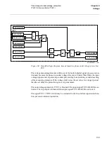
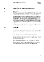
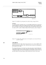
Setting Operation=Line test:
•
If the inputs LITE-TBCLOSED and LITE-START are activated and the line volt-
age is higher than the set value ULTest>, the timer is activated and the output signal
LITE-CLOSECB is activated when the time exceeds the set delay t. The signal
LITE-CLOSECB reverts after 200 ms.
Setting Operation=Voltage check:
•
A logical 1 is put on the input to the AND-gate in same way as with the setting Op-
eration=Line test, the function described above will become active.
•
If the voltage on both the line and busbar exceeds the set operate value ULnormal>
and UBnormal>, the output signal LITE-BLKTB is activated after a delay of 100
ms. If the input signal LITE-START is then activated, the output signal LITE-
CLOSECB is activated for 200 ms.
When the input signal LITE-TESTON is not activated and neither the line or busbar
voltage exceeds the set operate value, the output signal LITE-CLOSECB cannot be ac-
tivated.
An external signal, which is connected to input LITE-BLOCK, blocks the function. The
function is also blocked by the setting Operation=Off and with the setting Block-
LITE=Yes if the terminal is in test mode.
&DOFXODWLRQV
The parameters for the line test function are set via the local HMI or PST (Parameter
Setting Tool). Refer to the Technical reference manual for setting parameters and path
in local HMI.
The setting of the operate value for ULtest> must be lower than the lowest line voltage
on a line clear of faults when energised via the test breaker.
The setting of the operate value ULNormal> for the line voltage and UBnormal> for the
busbar voltage must be lower than the minimum expected operating voltage on the re-
spective line and busbar.
Set a safety margin of at least 10% to allow for the inaccuracy of the instrument trans-
formers, calculation methods and the terminal's measuring element.
Содержание REO 517
Страница 10: ... RQWHQWV ...
Страница 16: ...6 Introduction to the application manual KDSWHU QWURGXFWLRQ ...
Страница 64: ...54 Blocking of signals during test KDSWHU RPPRQ IXQFWLRQV ...
Страница 88: ...78 Scheme communication logic ZCOM KDSWHU LQH LPSHGDQFH ...
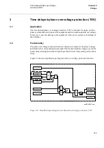
Страница 100: ...90 Time delayed phase and residual overcurrent protection TOC1 KDSWHU XUUHQW Equation 36 Iset IsSEC I1b 100 ...
Страница 146: ...136 Unbalance protection for capacitor banks TOCC KDSWHU XUUHQW ...
Страница 166: ...156 Dead line detection DLD KDSWHU 3RZHU V VWHP VXSHUYLVLRQ ...
Страница 171: ...161 About this chapter KDSWHU RQWURO KDSWHU RQWURO ERXW WKLV FKDSWHU This chapter describes the control functions ...
Страница 293: ...283 About this chapter KDSWHU RJLF KDSWHU RJLF ERXW WKLV FKDSWHU This chapter describes the logic functions ...
Страница 378: ...368 Monitoring of DC analog measurements KDSWHU 0RQLWRULQJ ...
Страница 379: ...369 About this chapter KDSWHU 0HWHULQJ KDSWHU 0HWHULQJ ERXW WKLV FKDSWHU This chapter describes the metering functions ...
Страница 384: ...374 Pulse counter logic PC KDSWHU 0HWHULQJ ...
Страница 412: ...402 Serial communication modules SCM KDSWHU DWD FRPPXQLFDWLRQ ...
Страница 440: ...430 LED indication module KDSWHU DUGZDUH PRGXOHV ...


