Serial Tunnel
Functions
2.21.2
Serial Protocols and Sampling Operation
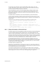
In general arbitrary serial UART format based protocols can be transported. The supported
remote control protocols are (among others) IEC 60870-5-101, Modbus, RCOM, RP570/RP571
and Hibus-2. Data rates up to 115200 Baud are supported, however the tunnel ends may be
configured with different baud rates. Also supported is the transmission of the break signal
that keeps the transmission on zero level for longer than an UART frame.
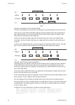
EDS500 devices support alternatively a special sampling operation ("transparent"), that
allows to transmit non-UART-compliant serial protocols and slow digital signals. For this the
transmit and receiving line must not be connected with TX or RX signal of the serial interface
Console0 or Console1 but with the CTS and RTS signal. For pin assignment refer to EDS500
Manual - Part 1: Serial Interfaces (Con0 - Con1).
Transmission of slow signals (<= 200 Baud) in sampling operation:
•
Quantity impulses for gas / water / electricity
•
Non EIA-232 compliant protocols
•
Alarm relais state, door contact, ...
Commands for configuration of the sampling operation:
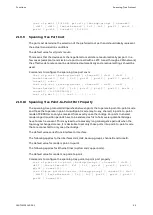
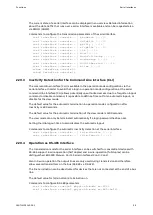
< s e t i n t e r f a c e { c o n s o l e 0 | c o n s o l e 1 } t r a n s p a r e n t { n o n e |
< s e t i n t e r f a c e { c o n s o l e 0 | c o n s o l e 1 } t r a n s p a r e n t { f a s t |
2.21.3
Topologies and Transmission settings
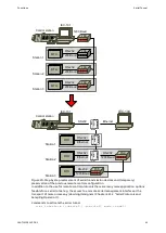
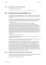
Data streams can be distributed in the Ethernet/IP network in various ways with a serial
tunnel. Depending on the extent and type of the network (Layer-2/switched vs. Layer-3/
routed) various logical topologies can be realized.
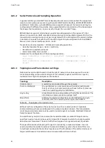
Topology
Description
Point-to-Point
A serial line is tunnelled through the network.
Point-to-Multipoint
One participant can communicate with all other participants
that in return cannot communicate with each other. Typical use
case for an existing partyline installation.
Any-to-Any
All participants can communicate with all other participants. The
simultaneous communication overlays itself.
Mixed form
Arbitrary transmission directions can be defined (even asym-
metrical). Like this a tapping mirroring can be realized.
Table 26: Topologies of the serial tunnel
Without further configuration the serial tunnel is set to a mode in which all reachable
communication partners are addressed in the same broadcast domain. This transmission
is not target-oriented and cannot be used in routed (Layer-3) networks. Multicast Ethernet
frame transport the data.
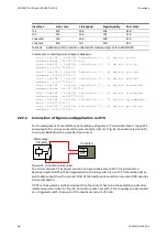
To avoid that any recipient can receive the transmitted data, so-called IP targets can be
specified. A serial tunnel can have up to 18 specific IP targets to which the incoming serial
data stream is forwarded. The data traffic then happens in targeted (unicast) IP packets.
This operation mode (while using IP targets) is mandatory in routed networks. It can be
used in switched networks to reduce the amount of data e.g. when the central office runs
in multicast mode while the stations have been set the IP address of the central device as IP
target (which means the stations cannot communicate with each other).
62
1KGT151021
V000 1
Содержание EDS500 Series
Страница 8: ...References Introduction 8 1KGT151021 V000 1 ...
Страница 152: ...Certificate Management Functions 152 1KGT151021 V000 1 ...
Страница 155: ...1KGT151021 V000 1 155 ...


