DSL Interfaces
Functions
To connect legacy devices of the HYTEC EDS series with actual devices via DSL you have to
activate the compatibility mode on both sides, refer to Chapter 2.15.5, "Configuration of Data
Encapsulation".
For a better identification of a connection in a topology each DSL interface can have a
description (alias).
The current link state of the DSL interface can be displayed in an overview. The link quality can
also be seen there. Detailed information about the data traffic that runs over an DSL interface
is also available and can be requested alternatively via RMON (SNMP). For a further analysis of
the connection state refer to Chapter 2.15.7, "Link Analysis" .
Commands to configure DSL interfaces
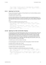
< s e t i n t e r f a c e { d s l 1 | d s l 2 } s h u t d o w n >
< s e t i n t e r f a c e { d s l 1 | d s l 2 } n o s h u t d o w n >
< s h o w i n t e r f a c e { d s l 1 | d s l 2 } >
< s h o w i n t e r f a c e { d s l 1 | d s l 2 } f r a m e - c o u n t e r s >
2.15.1
Process of Establishing Connection between DSL Interfaces
DSL interfaces can be activated and deactivated with commands.
The default value for all DSL interfaces is: shutdown.
Connection process:
1 A suitably DSL counterpart is discovered.
2 The connection properties are negotiated.
-> DSL Activity-LED flashes for up to a minute.
-> DSL Link-LED is off.
3 Link established successfully.
-> DSL Link-LED lit permanently.
-> DSL Activity-LED flashes to indicate payload traffic.
4 Link not established successfully.
-> Negotiation phase newly starts.
For details on LEDs see also EDS500 Manual - Part 1: Display Elements .
Commands to activate or deactivate the DSL interfaces
< s e t i n t e r f a c e { d s l 1 | d s l 2 } s h u t d o w n >
< s e t i n t e r f a c e { d s l 1 | d s l 2 } n o s h u t d o w n >
2.15.2
Configuration of the Mode (Master, Slave)
The operation mode of the interfaces of a DSL line has to be configured in such a way that the
interface on the one side is set to mode master and the interface on the other side is set to
mode slave.
The default value for mode of the interface dsl1 is master.
The default value for mode of the interface dsl2 is slave.
Commands can modify these settings as required.
Legacy EDS500 devices additionally have the setting Jumper, where the mode of interfaces
dsl1 and dsl2 is set by a hardware jumper on the main board.
The default valuemode on Legacy EDS devices is: jumper.
40
1KGT151021
V000 1
Содержание EDS500 Series
Страница 8: ...References Introduction 8 1KGT151021 V000 1 ...
Страница 152: ...Certificate Management Functions 152 1KGT151021 V000 1 ...
Страница 155: ...1KGT151021 V000 1 155 ...


