Serial Interfaces
Functions
•
8N1( 8 data bits, no parity, 1 stop bit)
•
no flow control
2.20.1
Usage for Configuration or as Process Interface
The default value for the serial interfaces is: configuration.
The setting configuration allows to access the management console with its command
line interface (CLI). An alternative use as process interface can be set with a command. The
following modes are available.
Mode
Parameter
Description
Configura-
tion
configura-
tion
The interface allows offers access to the command line interface (CLI) to con-
figure the device. This is the default value.
Modem
modem
The interface emulates an AT dial-up modem that can establish a link to
another emulated modem by using the IP address as dialled number.
Tunnel
tunnel
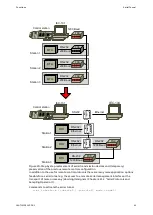
The interface transports serial data streams to one or more remote devices.
There, the data is output at the remote serial interface.
IEC101
iec101
The interface is set to telecontrol mode and can be attached to a IEC
60870-5-101 interface.
Linetest
linetest
The interface generates a test pattern that is sent continuously. With the com-
mand line interface (CLI) it can be monitored whether the interface receives
the test pattern correctly or whether the link is interrupted.
Loopback
loopback
The interface returns all received data immediately.
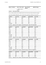
Table 25:
Operating modes
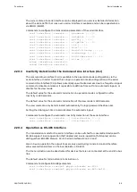
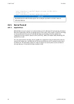
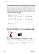
Commands to configure the operation mode of the serial interface
i e c 1 0 1 | l i n e t e s t | l o o p b a c k | m o d e m | t u n n e l } >
2.20.2
Transmission Parameters of the Interface
The parameters of the serial interface can be set by command for baud rate (300, 600, 1200,
2400, 4800, 9600, 19200, 38400, 57600, 115200 or 230400), data bits (5, 6, 7 or 8), parity
(none, even, odd, mark or space) and stop bits (1 or 2). Also the behaviour of the control
signals CTS and DCD can be set. The DCD signal can be inverted on hardware level.
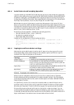
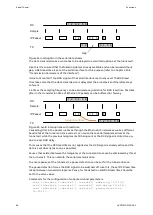
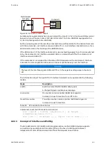
DCD lead times and follow-up times can be set for switching the carrier on or off if an
external modem is used. For this purpose DCD has to be set to while-tx. The DCD lead time
has an additional purpose for the operation mode “tunnel”, refer to "Serial Tunnel" .
TX
DCD
DCD Setup time
DCD Follow-Up time
Figure 19: DCD lead time and follow-up time
58
1KGT151021
V000 1
Содержание EDS500 Series
Страница 8: ...References Introduction 8 1KGT151021 V000 1 ...
Страница 152: ...Certificate Management Functions 152 1KGT151021 V000 1 ...
Страница 155: ...1KGT151021 V000 1 155 ...


