11-4 Example Connection Diagrams
3AXD50000011888
11.3 Motor Contactor or Shorting Contactor Examples
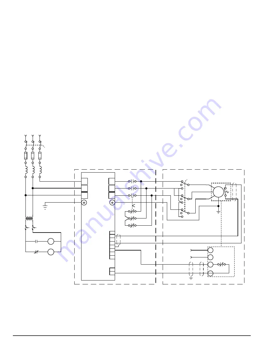
The following configurations are intended as examples on providing a manual motor disconnect or a power off fail safe
shorting contactor. These approaches can be used independent of the drive starting mode or reference source and are not
tied directly to the drive controller. Figure 11-3 depicts the preferred usage of a shorting contactor and a motor disconnect
when used with the N5350 drive.
11.3.1 Manual Motor Disconnect Switch
The motor disconnect should be located remotely from the drive panel, within site of the direct drive RPM AC motor and
driven load. This is in compliance with National Electric Code Sections 420.102 to 430.109. The switch should only be
shorted after the N5350 drive has been powered down or de-activated by opening the enable input.
11.3.2 Shorting Contactor
The intent of the Shorting Contactor is to provide one position (open) that is used when the fan is being run by the
N5350. This is the normal power on state. The other power off position (closed) shorts the motor leads together.
For both the options, the position that shorts the leads together is used to prohibit hazardous voltages from being present
on the motor leads when it is disconnected from the drive should the fan rotate. This could occur since the motor includes
permanent magnets in its rotor thus giving it the characteristics of being a generator when not connected to a drive. Another
benefit of this position is that it will cause the motor to resist wind-milling.
Figure 11-3 Motor Contactor Example
Cooling Tower Motor
M
Input Power
N.C. Dry
Contact Out
Customer Supplied
Vibration Switch
Customer Supplied
Vibration Sensor
Power Source
P2
P1
External Trip
Output Disconnect
SW2
Output Contactor
OC
Shorting Contactor
SC
OC
SC
OC
SC
115V
AC
T1
Select T1 Control transformer in
accordance with the input voltage
rating of the N5350
Input Power
Input Disconnect
SW1
Line Reactor
N5350+P934
T1/U
T2/V
T3/W
XDI
6
L1
L2
L3
1
2
3
4
5
J6
DICOM
DIIL
+24 VD
+24 VD
DIOGND
Ground Select
XD24
Содержание ACS880+N5350
Страница 1: ... ABB INDUSTRIAL DRIVES ACS880 N5350 cooling tower drives User s guide ...
Страница 32: ...Terminal Specifications 4 7 3AXD50000011888 Figure 4 3 Cable Conduit Installation R6 R7 R8 R9 ...
Страница 193: ...13 20 Troubleshooting 3AXD50000011888 ...
Страница 201: ...B 2 Dimensions 3AXD50000011888 Figure B 1 Frame R1 IP21 UL Type 1 Frame R1 IP21 UL Type 1 3AUA0000097621 ...
Страница 202: ...Dimensions B 3 3AXD50000011888 Figure B 2 Frame R2 IP21 UL Type 1 Frame R2 IP21 UL Type 1 3AUA0000097691 ...
Страница 203: ...B 4 Dimensions 3AXD50000011888 Figure B 3 Frame R3 IP21 UL Type 1 Frame R3 IP21 UL Type 1 3AUA0000097847 ...
Страница 206: ...Dimensions B 7 3AXD50000011888 Figure B 6 R6 IP21 UL Type 1 Frame R6 IP21 UL Type 1 3AUA0000098321 ...
Страница 207: ...B 8 Dimensions 3AXD50000011888 Figure B 7 Frame R7 IP21 UL Type 1 Frame R7 IP21 UL Type 1 3AUA0000073149 ...
Страница 208: ...Dimensions B 9 3AXD50000011888 Figure B 8 Frame R8 IP21 UL Type 1 Frame R8 IP21 UL Type 1 3AUA0000073150 ...
Страница 209: ...B 10 Dimensions 3AXD50000011888 Figure B 9 Frame R9 IP21 UL Type 1 Frame R9 IP21 UL Type 1 3AUA0000073151 ...
Страница 211: ...C 2 CE Guidelines 3AXD50000011888 Figure C 1 Declaration of Conformity ...
Страница 212: ...CE Guidelines C 3 3AXD50000011888 ...
Страница 244: ...Ethernet IP Setup G 3 3AXD50000011888 3 Click on New Module 4 Select Module Type ETHERNET MODULE ...
Страница 246: ...Ethernet IP Setup G 5 3AXD50000011888 8 The ACS880 CTD Drive is now added to the PLC I O ...


