5
tubing as opposed to nylon tubing. This is because nylon tubing tends to crimp shut when
it is bent. To remove the Unclamp Supply Line for service, make sure the air pressure is
discharged, then while pushing inward on the fitting's elastic ring, simultaneously pull the
tubing out. Cover or plug the self-locking fitting any time the Unclamp Supply Line is not
connected. This will keep contaminants from entering.
CLAMPING HOUSING
UNCLAMP AIR
PORT R 1/8 (METRIC)
FEEDBACK CONNECTOR
POWER CONNECTOR
MOTOR COOLING
PORTS R 1/8 (METRIC)
MOTOR HOUSING
30 TAPER MOTOR SHAFT
Printed Colors – Front:
Requester:
Marnie Cleveland
Creator:
deZinnia_25417
File Name:
External Features.ai
Structure #:
Illustration
Date:
04/24/19
This artwork has been created as requested by 3M. 3M is responsible for the artwork
AS APPROVED and assumes full responsibility for its correctness.
Scale:
1 Inch
Figure 8. External Features
Electrical Connections
The Servo Motors have two electrical connections, the Motor Power and Motor Feedback (See
Figure 8). The Motor Power and Motor Feedback connectors are shown in Figure 9. The collet
release mechanism relies solely on air pressure to operate; it requires no electrical connections.
Figure 9. Electrical Connector Pin-outs
Motor Cooling
The Servo Motors require water cooling. Each motor is designed to operate below a
temperature of 176°F (80°C). The optimal motor temperature range is 122-140°F (50-60°C).
The motors contain cooling channels in the Motor Housing surrounding the motor stator.
These channels allow efficient removal of the heat. The coolant enters and exits the Motor
Housing through two Motor Cooling Ports as shown in Figure 8. Either of these Motor Cooling
Ports can be used as an input, the other would then become an output. A closed-loop water
cooling system must be used and requires a separate cooling unit that circulates water
through the Motor Housing to remove the heat. All of the coolant is recirculated in the system,
and no continuous supply or discharge is required. A mixture of pure distilled water and a
corrosion inhibitor is required such as DowTherm SR-1, or equivalent. Typical cooling units
are comprised of a pump, water to air heat exchanger, and fan. These units are commercially
available from several manufacturers (e.g., Miller Coolmate 3, www.millerwelds.com). The
cooling unit should be sized based on the motor power output of 3.0 hp (2.2 kW) or 5.0
hp (3.7 kW) with an overall motor efficiency of 90% and the motor load conditions. It is
recommended to constantly monitor the motor temperature during operation to ensure that it
does not overheat.
NOTE: The life of the motor is directly related to the operational temperature, so proper
cooling is critical.
Two 1/4” and 6 mm diameter tube push-lock fittings are provided for installation in the Motor
Cooling Ports. Remove the shipping plugs and install the desired size push-lock fittings. If
another type of fitting is needed, replace the existing fitting with a fitting having an R 1/8
(Metric) thread. Be sure to use a thread seal product and do not overtighten the fitting.
Monitoring Motor Temperature
The Servo Motors are designed to operate below a temperature of 176°F (80°C) and within an
optimal range of 122-140°F (50-60°C). In many situations it is desirable to monitor the internal
motor temperature to ensure that the maximum temperature rating is not exceeded, and that
the optimal temperature range is maintained. To facilitate this, each motor has a thermistor
that is embedded in the motor windings. The thermistor connection is provided on the Motor
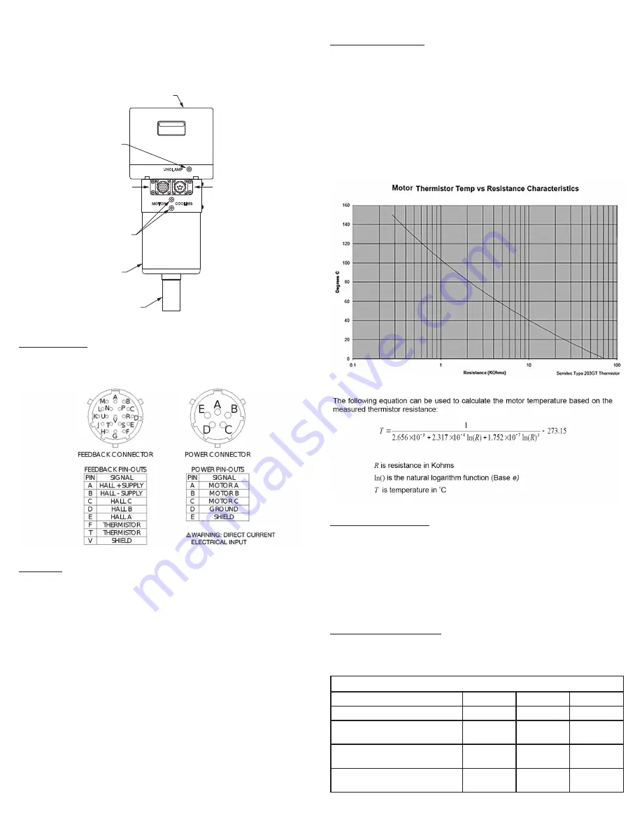
Feedback Connector as shown in Figure 9. The thermistor temperature signal is a logarithmic
function of the output resistance. The graph shown in Figure 10 illustrates the internal motor
temperature verses the thermistor output resistance. In the graph, a temperature of 176°F
(80°C) corresponds to a resistance of 2000 ohms. If the thermistor indicates a resistance of
less than 2000 ohms then the motor should be immediately shut down before thermal damage
occurs. The motor also contains a thermal cutoff switch. If the temperature exceeds 212°F
(100°C) the motor will stop running until it has cooled off. This feature should not be used to
control the motor temperature. The thermal cutoff is designed to operate only when all other
precautions have failed.
Figure 10. Thermistor Chart
Figure 11. Temperature - Resistance Equation
Motor Acceleration/Deceleration
Servo Motors have the ability to start and stop very quickly. As long as the motor does not
overheat or the amplifier exceed the allowable current input, the motor will continue to
operate. The problem is that the motor and amplifier can experience excessive current spikes
with rapid acceleration and deceleration. Media or tooling with a large mass or large diameter
(i.e., high moment of inertia) only increases the current surge. The amount of time allowed
to reach the desired speed or stop will directly affect the life of the motor. 3M recommends a
smooth, linear velocity ramp with a minimum period of one second be used to accelerate to
full speed or to decelerate to zero speed. The minimum one-second-acceleration period must
be increased if larger, higher inertia tools are used to prevent servo amplifier faults and avoid
long-term damage.
Preventative Maintenance Schedule
It is highly recommended to adhere to the preventative maintenance schedule in order to help
extend the longevity of the equipment. Failing to do so could cause a loss in functionality as
well as a decrease in product life.
3M SPINDLES
Maintenance
Weekly
Monthly
3 Months
Remove chips from the ID of the shaft
X
Remove debris from spindle/spindle
housing
X
Check that the connectors are not bent/
damaged
X
Check for flow in the motor cooling and
unclamp ports
X


