manualshive.com logo in svg
background image

4

3M 06531 

3M 06532

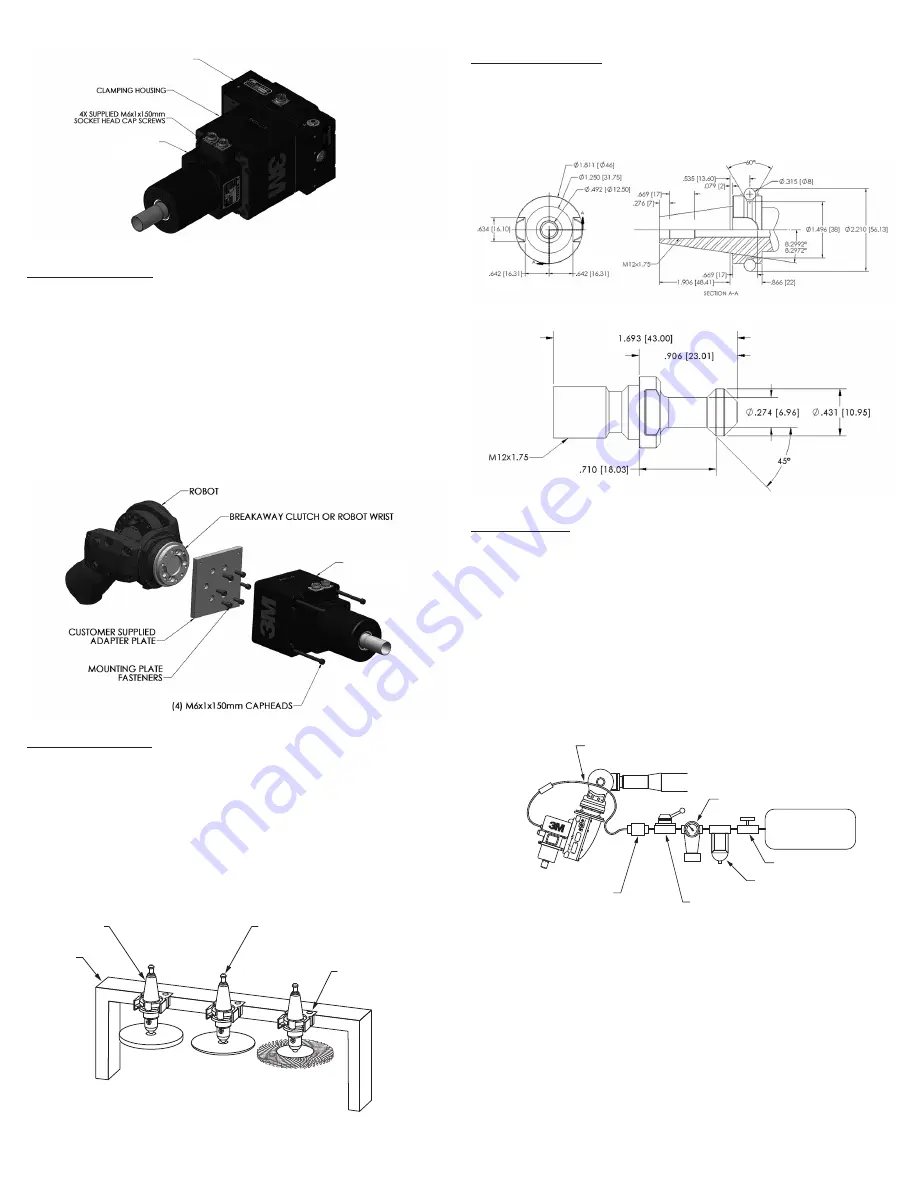
Figure 2. Spindle Motor Perpendicular-Axis Configuration

Mounting Directly to a Robot

For some processes compliance and force control are not required. The tools can be mounted 

directly to the robot, in these cases, and the system can be operated in position mode. This 

robotic system is equivalent to a 5-axis machining center with a very large work volume and 

lower positional accuracy. Certain product types and processes are well suited for a Robotic 

Machining Center (RMC). The tools can be attached to the Robot Mounting Flange using a 

customer supplied Mounting Plate. For direct mounting it is recommended that a Breakaway 

Clutch is installed. The Breakaway Clutch will help protect the motor in the event of a robot 

crash. Loads on the motor shaft of over 300 lb (136 kg) radially and 150 (68 kg) axially will 

damage the bearings.

To mount the tool, first attach the customer supplied Mounting Plate to the Robot Mounting 

Flange or to the Breakaway Clutch, per the manufacturer’s specifications. Once the Mounting 

Plate is secured, place the tool against the Mounting Plate and install four (4) M6x1x145mm 

Socket Head Cap Screws. (See Figure 3.) Tighten the fasteners to the torque specified in the 

Technical Specifications Section.

3M 06531 

3M 06532

Figure 3. Spindle Motor Direct Mounting

Media and Tool Presentation

Media and tool presentation refers to how various discs, drill bits, router bits, etc. are 

presented so that a robot may maneuver the motor into position to grasp the Toolholder 

reliably. It is ultimately the user’s responsibility to provide a means to present the media and/

or tooling in an effective and repeatable way for a given application.

As shown in Figure 4, many types of media and tools may be accurately located in a Tool 

Cradle. A robot can then be taught approach paths and docking locations to reliably bring the 

motor down over the Toolholders and grasp them. The motor’s Collapsing Collet allows  

0.015 in. (0.38 mm) diametrical clearance around the Toolholder when open. The Toolholder 

must have a taper that mates to a Tapered Holder mounted in the Tool Cradle. The Tapered 

Holder requires a slot to allow the Toolholder to pass through. This same method is applicable 

to the motor’s design.

BT30 TOOLHOLDER

BT30 TOOLHOLDER GRIPPER

BT30 RETENTION KNOB

TOOL RACK

Printed Colors – Front:

Requester:

  Marnie Cleveland

Creator:

 deZinnia_25417

File Name:

  Sample Media and Tooling Presentation Scheme.ai

Structure #:

  Illustration  

Date:

 04/24/19

This artwork has been created as requested by 3M. 3M is responsible for the artwork 
AS APPROVED and assumes full responsibility for its correctness.

Scale:

1 Inch

Figure 4. Sample Media and Tooling Presentation Scheme

BT30 Toolholder Specification

The 3M Model 06531 and 06532 motors are designed to grip a BT30 Toolholder. The BT30 

Toolholder is a standard machine tool style and may be purchased from 3M (Part Number 

06534, 5/8-11 X .48IN BT30 TOOLHOLDER HTC): The Customer can also make their own BT30 

Toolholder to handle special media (See Figure 5 for Toolholder dimensions). The Toolholder 

must be equipped with a Parlec (www.parlec.com) retention knob, part number 3003TRK, or 

equivalent. Figure 6 shows the Parlec retention knob with the required dimensions.

Figure 5. STC-BT30 Toolholder Dimensions

Figure 6. BT30 Retention Knob

Pneumatic Connection

The Tool Changing function of the motor requires a dry, non-lubricated, filtered air supply, 

with a minimum pressure of 90 psi (6.2 bar) and a maximum pressure of 100 psi (6.9 bar). 

Failure to provide supply air to these specifications can degrade performance and will void any 

warranty repairs concerning pneumatic components. If the supply air pressure is too low then 

the unit will be unable to fully release the Toolholder. Exceeding the maximum air pressure 

could result in permanent damage to the Tool Changing function. The pneumatic supply system 

should be configured as shown in Figure 7. A manual or electrically operated valve may be 

used to energize the Tool Changing function for Toolholder release, but the valve must exhaust 

ALL line pressure when unenergized. An electrically operated pneumatic valve is normally 

used in an automated workcell. 3M highly recommends the installation of a Pressure Switch 

in the Supply Line to the Servo Motor. This switch should not allow the unit to start if there is 

any pressure in the Supply Line. Pressure in the line will cause internal components to come 

into contact. This will either cause the motor not to spin, or cause very high internal forces, 

eventually friction welding components together.

Air Regulator/Pressure Gauge

1/4" (6mm) Polyurethane 

Tubing

Manual or Electrically 

Operated Valve

5µm Filter

Shut off Valve

90 psi minimum 

(6.2 Bar) 

Dry, Non-lubricated

Air Supply

Pressure Switch

Quick 

Exhaust

Printed Colors – Front:

Requester:

  Marnie Cleveland

Creator:

 deZinnia_25417

File Name:

  Pneumatic Connections.ai

Structure #:

  Illustration  

Date:

 04/24/19

This artwork has been created as requested by 3M. 3M is responsible for the artwork 
AS APPROVED and assumes full responsibility for its correctness.

Scale:

1 Inch

Figure 7. Pneumatic Connections

The motors are provided with 1/4 inch and 6 mm diameter tubing push-lock fittings for 

installation in the R 1/8 (Metric) Collet Unclamp Port located on the top of the Clamping 

Housing (See Figure 8). Remove the shipping plug and install the desired size push-lock fitting. 

If another type of fitting is desired, unscrew the existing fitting and replace it with any fitting 

having an R 1/8 (Metric) thread. Be sure to use a thread seal product and do not overtighten 

the fitting. The Unclamp Supply Line to the device should be 1/4 inch or 6 mm diameter flexible 

polyurethane tubing. The tubing should be routed to the device such that there are no kinks 

and that there is plenty of slack to allow for manipulator motion. Before inserting the tubing 

into the air fitting, open the Shut-Off Valve to blow out any contaminants which may be in the 

Unclamp Supply Line. The tubing can now be pushed into the self-locking fitting located on the 

Clamping Housing as shown in Figure 8. Charge the Unclamp Supply Line with compressed 

air and verify that there are no air leaks and that there is a minimum of 90 PSI (6.2 bar) at the 

Servo Motor. If a minimum air pressure cannot be achieved, then an auxiliary air compressor or 

booster pump must be installed. NOTE: 3M highly recommends the use of flexible polyurethane 

ACT

Содержание 06531

Страница 1: ...ing safety information Marking Description WARNING READ AND UNDERSTAND INSTRUCTION MANUAL BEFORE OPERATING TOOL WARNING ALWAYS WEAR APPROVED EYE PROTECTION INTERNATIONAL ELECTRICAL SAFETY CERTIFICATION SYMBOL WARNING DIRECT CURRENT ELECTRICAL INPUT PROTECTIVE EARTH GROUND POINT 3Ø VOLTAGE THREE PHASE VOLTAGE RATING RMS RATED SPEED MAXIMUM OPERATING SPEED RPM OUTPUT RATING MAXIMUM POWER OUTPUT WATT...

Страница 2: ...ds of tool holder Ensure the device is in an appropriate power state for maintenance change over service and testing NOTICE Do not run the motor power cable in close proximity to any feedback or control cables because of possible electrical noise problems The life of the motor is directly related to the operational temperature so proper cooling is critical 3M recommends the use of flexible polyure...

Страница 3: ...ing the unit above 176 F 80 C will cause the rotor to de magnetize and the bearings to fail High temperatures will also cause the O rings that seal the cooling water channels to fail possibly filling the motor with water Flow through water cooling is provided on the motor to allow high duty cycles without overheating Product Configuration Specifications Operating Maintenance Instructions Model Pow...

Страница 4: ...Figure 6 BT30 Retention Knob Pneumatic Connection The Tool Changing function of the motor requires a dry non lubricated filtered air supply with a minimum pressure of 90 psi 6 2 bar and a maximum pressure of 100 psi 6 9 bar Failure to provide supply air to these specifications can degrade performance and will void any warranty repairs concerning pneumatic components If the supply air pressure is t...

Страница 5: ...ion in the Motor Cooling Ports Remove the shipping plugs and install the desired size push lock fittings If another type of fitting is needed replace the existing fitting with a fitting having an R 1 8 Metric thread Be sure to use a thread seal product and do not overtighten the fitting Monitoring Motor Temperature The Servo Motors are designed to operate below a temperature of 176 F 80 C and with...

Страница 6: ...NTY OR CONDITION OF MERCHANTABILITY FITNESS FOR A PARTICULAR PURPOSE OR ARISING OUT OF A COURSE OF DEALING CUSTOM OR USAGE OF TRADE If a 3M product does not conform to this warranty then the sole and exclusive remedy is at 3M s option replacement of the 3M product or refund of the purchase price 3 Abrasive Systems Division 3M Center St Paul MN 55144 1000 U S A www 3M com abrasives 3M 2019 3M is a ...

Страница 7: ... D UTILISATION AVANT DE SE SERVIR DE L OUTIL MISE EN GARDE TOUJOURS PORTER UN DISPOSITIF DE PROTECTION OCULAIRE HOMOLOGUÉ SYMBOLE INTERNATIONAL DE CERTIFICATION DE SÉCURITÉ ÉLECTRIQUE MISE EN GARDE PUISSANCE ABSORBÉE À COURANT CONTINU POINT DE MISE À LA TERRE DE PROTECTION TENSION 3Ø TENSION NOMINALE TRIPHASÉE TENSION EFFICACE VITESSE NOMINALE RÉGIME D UTILISATION MAXIMAL TR MIN PUISSANCE NOMINALE...

Страница 8: ...mentation approprié pour l entretien l inversion la réparation et les essais AVIS Ne pas faire passer le câble d alimentation du moteur à proximité de câbles de renvoi ou de commande en raison des problèmes de bruit électrique possibles La durée de vie du moteur étant directement liée à la température de fonctionnement un refroidissement approprié est essentiel 3M recommande l utilisation d un tuy...

Страница 9: ...it Directives d utilisation et d entretien Modèle Puissance en HP kW Couple de maintien continu en lb pi N m Pleine charge A Régime maximal en tr min Régulation de vitesse en Charge axiale maximale de l arbre en lb N Charge radiale maximale de l arbre en lb N Poids en lb kg Température de fonctionnement optimale en C F maximal Blocage thermique en C F Pression maximale du liquide de refroidissemen...

Страница 10: ... Sample Media and Tooling Presentation Scheme ai Structure Illustration Date 04 24 19 This artwork has been created as requested by 3M 3M is responsible for the artwork AS APPROVED and assumes full responsibility for its correctness Scale 1 Inch Figure 4 Exemple de schéma de présentation des matériaux et des outils Spécifications du porte outil BT30 Les modèles de moteur 3M 06531 et 06532 sont con...

Страница 11: ...ment du moteur Les servomoteurs nécessitent un refroidissement à l eau Chaque moteur est conçu pour fonctionner à une température inférieure à 80 C 176 F La plage de température optimale du moteur est de 50 à 60 C 122 à 140 F Les moteurs contiennent des canaux de refroidissement dans le boîtier du moteur entourant le stator du moteur Ces canaux permettent une évacuation efficace de la chaleur Le l...

Страница 12: ...valuer le produit et d établir s il convient à l application prévue y compris effectuer une évaluation des dangers présents dans le lieu de travail et passer en revue tous les règlements applicables à sa région p ex OSHA ANSI etc Le fait de ne pas bien évaluer sélectionner et utiliser un produit 3M ainsi que les produits de sécurité appropriés ou de ne pas respecter toutes les règles de sécurité p...

Страница 13: ...ridad Marca Descripción ADVERTENCIA LEA Y COMPRENDA EL MANUAL DE INSTRUCCIONES ANTES DE OPERAR LA HERRAMIENTA ADVERTENCIA USE SIEMPRE LA PROTECCIÓN OCULAR APROBADA SÍMBOLO DE CERTIFICACIÓN INTERNACIONAL DE SEGURIDAD ELÉCTRICA ADVERTENCIA ENTRADA ELÉCTRICA DE CORRIENTE CONTINUA PUNTO DE PUESTA A TIERRA PROTECTORA VOLTAJE DE 3Ø CLASIFICACIÓN DE VOLTAJE TRIFÁSICO RMS VELOCIDAD NOMINAL VELOCIDAD MÁXIM...

Страница 14: ... en un estado de alimentación adecuado para mantenimiento cambio reparación y pruebas ADVERTENCIA AVISO No pase el cable de alimentación del motor cerca de cualquier cable de retroalimentación o control debido a posibles problemas de ruido eléctrico La vida útil del motor está directamente relacionada con la temperatura de operación por lo que un enfriamiento adecuado es fundamental 3M recomienda ...

Страница 15: ...e 80 C 176 F El funcionamiento continuo de la unidad por encima de 80 C 176 F hará que el rotor se desmagnetice y los cojinetes fallen Las altas temperaturas también Especificaciones configuración del producto Instrucciones de uso y mantenimiento Modelo Potencia HP kW Torque de bloqueo continuo lb pies N M Carga completa A Velocidad máxima RPM Regulación de velocidad Carga axial máxima del eje lb ...

Страница 16: ...24 19 This artwork has been created as requested by 3M 3M is responsible for the artwork AS APPROVED and assumes full responsibility for its correctness Scale 1 Inch Figura 4 Ejemplo de esquema de presentación de medios abrasivos y herramientas Especificación del portaherramientas BT30 Los motores modelo 06531 y 06532 de 3M están diseñados para sujetar un portaherramientas BT30 El portaherramienta...

Страница 17: ...ector eléctrico Enfriamiento del motor Los servomotores requieren refrigeración por agua Cada motor está diseñado para funcionar por debajo de una temperatura de 80 C 176 F El rango óptimo de temperatura del motor es 50 60 C 122 140 F Los motores contienen canales de enfriamiento en la carcasa del motor que rodea su estator Estos canales permiten la eliminación eficiente del calor El refrigerante ...

Страница 18: ...o responsable de evaluar el producto y determinar si es apropiado y adecuado para su aplicación incluida la realización de una evaluación de peligros en el lugar de trabajo y la revisión todas las normativas y normas aplicables por ej OSHA ANSI etc No evaluar seleccionar y utilizar correctamente un producto de 3M y los productos de seguridad correspondientes o no cumplir con todos los reglamentos ...

Отзывы: