manualshive.com logo in svg
background image

3

General Overview

The 3M Model 06531 13300 RPM, 3 HP and 3M Model 06532 6000 RPM, 5 HP Servo Rotary 

Tool share many common components. The 13300 and 6000 RPM motors are capable of 

continuously producing 3 and 5 horsepower respectively. The motors use a BT30 Toolholder 

which allows changing out tools and media. Each of these motors provide a convenient and 

effective means to spin and/or change any number of different media types to support a fully 

automated workcell.

These automatic tool-changing models actuate pneumatically to secure the BT30 style 

Toolholder. They are comprised of four primary components: a high-torque Servo Motor, a 

pneumatic actuator, high force Belleville springs, and a component to clamp a Toolholder. 

These models use a drawbar to pull the Collet/Gripper in. High force Belleville springs located 

at the back of the Servo Motor tension the drawbar. Actuating the large pneumatic actuator, 

located in the Clamping Housing, opens the Collet/Gripper. During pressurization the cylinder 

contacts the Belleville springs and compresses them to drive the Collet/Gripper out, releasing 

the Toolholder. There is no mechanism to forcibly eject the Toolholder from the Collet, so 

gravity or a capturing mechanism must be used. Both models use a 30 taper to grip a 

standard BT30 Toolholder. This design locks the Toolholder in the 30 tapered shaft and resists 

large pull out forces. The shaft does not have locking keys, so motor indexing for tool change 

is not required.

These automatic tool-changing motors are fail-safe, in that no air pressure is required to hold 

the Toolholder. Therefore, the Toolholder will remain held in the Collet/Gripper even when 

the air pressure is unexpectedly lost. Likewise, applying air pressure to a single input port 

via a simple manual or electrically operated valve opens the Collet/Gripper and releases the 

Toolholder. The design always isolates the motor bearings from the drawbar tension. This 

greatly improves reliability by allowing the motor shaft to spin freely and never be subject to 

any clamping forces. Both motors use sealed bearings to ensure a long life. The bearings have 

additional contamination protection from a contact shaft seal. This special seal eliminates the 

need for constant purge air.

During operation these motors generate considerable heat due to their high torque and 

compact size. Excessive operating temperatures will significantly reduce the life of the motors. 

Water Cooling is required to keep the unit within the internal temperature operating range. 

The motor should never be allowed to exceed a temperature of 176˚F (80˚C). Continuously 

operating the unit above 176˚F (80˚C) will cause the rotor to de-magnetize and the bearings to 

fail. High temperatures will also cause the O-rings that seal the cooling water channels to fail, 

possibly filling the motor with water. Flow through water cooling is provided on the motor to 

allow high duty cycles without overheating.

Product Configuration / Specifications

Operating / Maintenance Instructions

Model

Power 

HP 

(kW)

Continuous 

Stall 

Torque  

lb.-ft. (N·m)

Full Load 

(A)

Maximum 

Speed 

RPM

Speed 

Regulation 

%

Shaft 

Maximum 

Axial 

Load lb. 

(N)

Shaft 

Maximum 

Radial 

Load lb. 

(N)

Weigh 

lb. (kg)

Operating 

Temperature 

Optimal, 

Maximum 

F (C)

Thermal 

Cutoff F 

(C)

Max. 

Coolant 

Pressure: 

PSI (Bar)

Insulation

Amplifier Type

06531

(2.2)

2.57 (3.5)

15.0

13300

Reversible

150 (666)

300 

(1332)

28 

(12.7)

122, 176  

(60, 80)

212 

(100)

60 (4.1)

Class F 

(155°C)

Kollmorgen

®


Servo Amplifier 

13300, 3M PN 

06547

06532

(3.7)

5.6 (7.6)

19.5

6000

Reversible

150 (666)

300 

(1332)

28 

(12.7)

122, 176  

(60, 80)

212 

(100)

60 (4.1)

Class F 

(155°C)

Kollmorgen

®


Servo Amplifier 

0605, 3M PN 

06545

Fastener Tightening Torque Specs

Torque

Minimum Depth

Fastener Size

in.-lbs.

ft.-lbs.

N-m

in.

mm

M4 x .7

50

4.2

5.6

0.17

4.3

M5 x .8

85

7.1

9.6

0.21

5.3

M6 x 1

140

11.7

15.8

0.25

6.3

M8 x 1.25

348

29.0

39.3

0.33

8.4

M10 x 1.5

600

50.0

67.8

0.41

10.5

Installation & Operation

Mounting the 3M rotary tool to a 3M ACT compliant tool

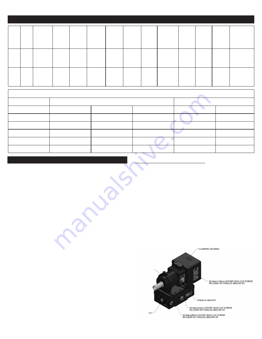
The tools are designed to attach directly to the Carriage of 3M ACT (Active Compliant Tool), 

using the Parallel Mounting Kit Model 06533.

The Parallel-Axis configuration is shown in Figure 1, where the tool attaches to the ACT 

Carriage with the Parallel Mounting Kit. The Parallel Mounting Kit is positioned on the Carriage 

and attached using the four (4) supplied M6x1x20mm Socket Head Cap Screws. The tool is 

then attached to the Parallel Mounting Kit as shown, with two (2) M6x1x20mm Socket Head 

Cap Screws into the front of the Motor Housing. Two (2) M6x1x145mm Socket Head Cap 

Screws pass through the Clamping Housing/Mounting Plate. The fasteners must be tightened 

to the torque specified in the Technical Specifications Section.

To attach the tool to an ACT in a Perpendicular-Axis configuration, position the Clamping 

Housing/Mounting Plate over the Carriage as shown in Figure 2. Then secure the unit using 

four (4) M6x1x145mm Socket Head Cap Screws. Tighten the fasteners to the torque specified 

the Technical Specifications Section. 5mm Dowel pins can be inserted and glued into the 

Carriage to align the motor. The Clamping Housings and Mounting Plate have predrilled 

clearance dowel holes for this configuration.

NOTICE: Make sure that the M6x1 fasteners do not exceed a depth of 0.40” (10 mm) into 

the ACT Carriage Helicoils or damage will occur.

NOTICE: Do not press Dowel Pins into the ACT Carriage, this will damage the linear rails.

3M 06531 

3M 06532

Figure 1. Spindle Motor Parallel-Axis Configuration

Содержание 06531

Страница 1: ...ing safety information Marking Description WARNING READ AND UNDERSTAND INSTRUCTION MANUAL BEFORE OPERATING TOOL WARNING ALWAYS WEAR APPROVED EYE PROTECTION INTERNATIONAL ELECTRICAL SAFETY CERTIFICATION SYMBOL WARNING DIRECT CURRENT ELECTRICAL INPUT PROTECTIVE EARTH GROUND POINT 3Ø VOLTAGE THREE PHASE VOLTAGE RATING RMS RATED SPEED MAXIMUM OPERATING SPEED RPM OUTPUT RATING MAXIMUM POWER OUTPUT WATT...

Страница 2: ...ds of tool holder Ensure the device is in an appropriate power state for maintenance change over service and testing NOTICE Do not run the motor power cable in close proximity to any feedback or control cables because of possible electrical noise problems The life of the motor is directly related to the operational temperature so proper cooling is critical 3M recommends the use of flexible polyure...

Страница 3: ...ing the unit above 176 F 80 C will cause the rotor to de magnetize and the bearings to fail High temperatures will also cause the O rings that seal the cooling water channels to fail possibly filling the motor with water Flow through water cooling is provided on the motor to allow high duty cycles without overheating Product Configuration Specifications Operating Maintenance Instructions Model Pow...

Страница 4: ...Figure 6 BT30 Retention Knob Pneumatic Connection The Tool Changing function of the motor requires a dry non lubricated filtered air supply with a minimum pressure of 90 psi 6 2 bar and a maximum pressure of 100 psi 6 9 bar Failure to provide supply air to these specifications can degrade performance and will void any warranty repairs concerning pneumatic components If the supply air pressure is t...

Страница 5: ...ion in the Motor Cooling Ports Remove the shipping plugs and install the desired size push lock fittings If another type of fitting is needed replace the existing fitting with a fitting having an R 1 8 Metric thread Be sure to use a thread seal product and do not overtighten the fitting Monitoring Motor Temperature The Servo Motors are designed to operate below a temperature of 176 F 80 C and with...

Страница 6: ...NTY OR CONDITION OF MERCHANTABILITY FITNESS FOR A PARTICULAR PURPOSE OR ARISING OUT OF A COURSE OF DEALING CUSTOM OR USAGE OF TRADE If a 3M product does not conform to this warranty then the sole and exclusive remedy is at 3M s option replacement of the 3M product or refund of the purchase price 3 Abrasive Systems Division 3M Center St Paul MN 55144 1000 U S A www 3M com abrasives 3M 2019 3M is a ...

Страница 7: ... D UTILISATION AVANT DE SE SERVIR DE L OUTIL MISE EN GARDE TOUJOURS PORTER UN DISPOSITIF DE PROTECTION OCULAIRE HOMOLOGUÉ SYMBOLE INTERNATIONAL DE CERTIFICATION DE SÉCURITÉ ÉLECTRIQUE MISE EN GARDE PUISSANCE ABSORBÉE À COURANT CONTINU POINT DE MISE À LA TERRE DE PROTECTION TENSION 3Ø TENSION NOMINALE TRIPHASÉE TENSION EFFICACE VITESSE NOMINALE RÉGIME D UTILISATION MAXIMAL TR MIN PUISSANCE NOMINALE...

Страница 8: ...mentation approprié pour l entretien l inversion la réparation et les essais AVIS Ne pas faire passer le câble d alimentation du moteur à proximité de câbles de renvoi ou de commande en raison des problèmes de bruit électrique possibles La durée de vie du moteur étant directement liée à la température de fonctionnement un refroidissement approprié est essentiel 3M recommande l utilisation d un tuy...

Страница 9: ...it Directives d utilisation et d entretien Modèle Puissance en HP kW Couple de maintien continu en lb pi N m Pleine charge A Régime maximal en tr min Régulation de vitesse en Charge axiale maximale de l arbre en lb N Charge radiale maximale de l arbre en lb N Poids en lb kg Température de fonctionnement optimale en C F maximal Blocage thermique en C F Pression maximale du liquide de refroidissemen...

Страница 10: ... Sample Media and Tooling Presentation Scheme ai Structure Illustration Date 04 24 19 This artwork has been created as requested by 3M 3M is responsible for the artwork AS APPROVED and assumes full responsibility for its correctness Scale 1 Inch Figure 4 Exemple de schéma de présentation des matériaux et des outils Spécifications du porte outil BT30 Les modèles de moteur 3M 06531 et 06532 sont con...

Страница 11: ...ment du moteur Les servomoteurs nécessitent un refroidissement à l eau Chaque moteur est conçu pour fonctionner à une température inférieure à 80 C 176 F La plage de température optimale du moteur est de 50 à 60 C 122 à 140 F Les moteurs contiennent des canaux de refroidissement dans le boîtier du moteur entourant le stator du moteur Ces canaux permettent une évacuation efficace de la chaleur Le l...

Страница 12: ...valuer le produit et d établir s il convient à l application prévue y compris effectuer une évaluation des dangers présents dans le lieu de travail et passer en revue tous les règlements applicables à sa région p ex OSHA ANSI etc Le fait de ne pas bien évaluer sélectionner et utiliser un produit 3M ainsi que les produits de sécurité appropriés ou de ne pas respecter toutes les règles de sécurité p...

Страница 13: ...ridad Marca Descripción ADVERTENCIA LEA Y COMPRENDA EL MANUAL DE INSTRUCCIONES ANTES DE OPERAR LA HERRAMIENTA ADVERTENCIA USE SIEMPRE LA PROTECCIÓN OCULAR APROBADA SÍMBOLO DE CERTIFICACIÓN INTERNACIONAL DE SEGURIDAD ELÉCTRICA ADVERTENCIA ENTRADA ELÉCTRICA DE CORRIENTE CONTINUA PUNTO DE PUESTA A TIERRA PROTECTORA VOLTAJE DE 3Ø CLASIFICACIÓN DE VOLTAJE TRIFÁSICO RMS VELOCIDAD NOMINAL VELOCIDAD MÁXIM...

Страница 14: ... en un estado de alimentación adecuado para mantenimiento cambio reparación y pruebas ADVERTENCIA AVISO No pase el cable de alimentación del motor cerca de cualquier cable de retroalimentación o control debido a posibles problemas de ruido eléctrico La vida útil del motor está directamente relacionada con la temperatura de operación por lo que un enfriamiento adecuado es fundamental 3M recomienda ...

Страница 15: ...e 80 C 176 F El funcionamiento continuo de la unidad por encima de 80 C 176 F hará que el rotor se desmagnetice y los cojinetes fallen Las altas temperaturas también Especificaciones configuración del producto Instrucciones de uso y mantenimiento Modelo Potencia HP kW Torque de bloqueo continuo lb pies N M Carga completa A Velocidad máxima RPM Regulación de velocidad Carga axial máxima del eje lb ...

Страница 16: ...24 19 This artwork has been created as requested by 3M 3M is responsible for the artwork AS APPROVED and assumes full responsibility for its correctness Scale 1 Inch Figura 4 Ejemplo de esquema de presentación de medios abrasivos y herramientas Especificación del portaherramientas BT30 Los motores modelo 06531 y 06532 de 3M están diseñados para sujetar un portaherramientas BT30 El portaherramienta...

Страница 17: ...ector eléctrico Enfriamiento del motor Los servomotores requieren refrigeración por agua Cada motor está diseñado para funcionar por debajo de una temperatura de 80 C 176 F El rango óptimo de temperatura del motor es 50 60 C 122 140 F Los motores contienen canales de enfriamiento en la carcasa del motor que rodea su estator Estos canales permiten la eliminación eficiente del calor El refrigerante ...

Страница 18: ...o responsable de evaluar el producto y determinar si es apropiado y adecuado para su aplicación incluida la realización de una evaluación de peligros en el lugar de trabajo y la revisión todas las normativas y normas aplicables por ej OSHA ANSI etc No evaluar seleccionar y utilizar correctamente un producto de 3M y los productos de seguridad correspondientes o no cumplir con todos los reglamentos ...

Отзывы: