VES-1124 User’s Guide
Hardware Connections
3-3
Table 3-2 LED Descriptions
LED COLOR
STATUS
DESCRIPTION
Off
The system is functioning normally.
On
The link to the VDSL modem is up.
VDSL
(1~24)
Green
Off
The link to the VDSL modem is down.
Blinking
The system is transmitting/receiving to/from a 10 Mbps Ethernet
network.
On
The link to a 10 Mbps Ethernet network is up.
Green
Off
The link to a 10 Mbps Ethernet network is down.
Blinking
The system is transmitting/receiving to/from a 100 Mbps Ethernet
network.
On
The link to a 100 Mbps Ethernet network is up.
10/100
(25, 26)
Yellow
Off
The link to a 100 Mbps Ethernet network is down.
3.3 Rear Panel
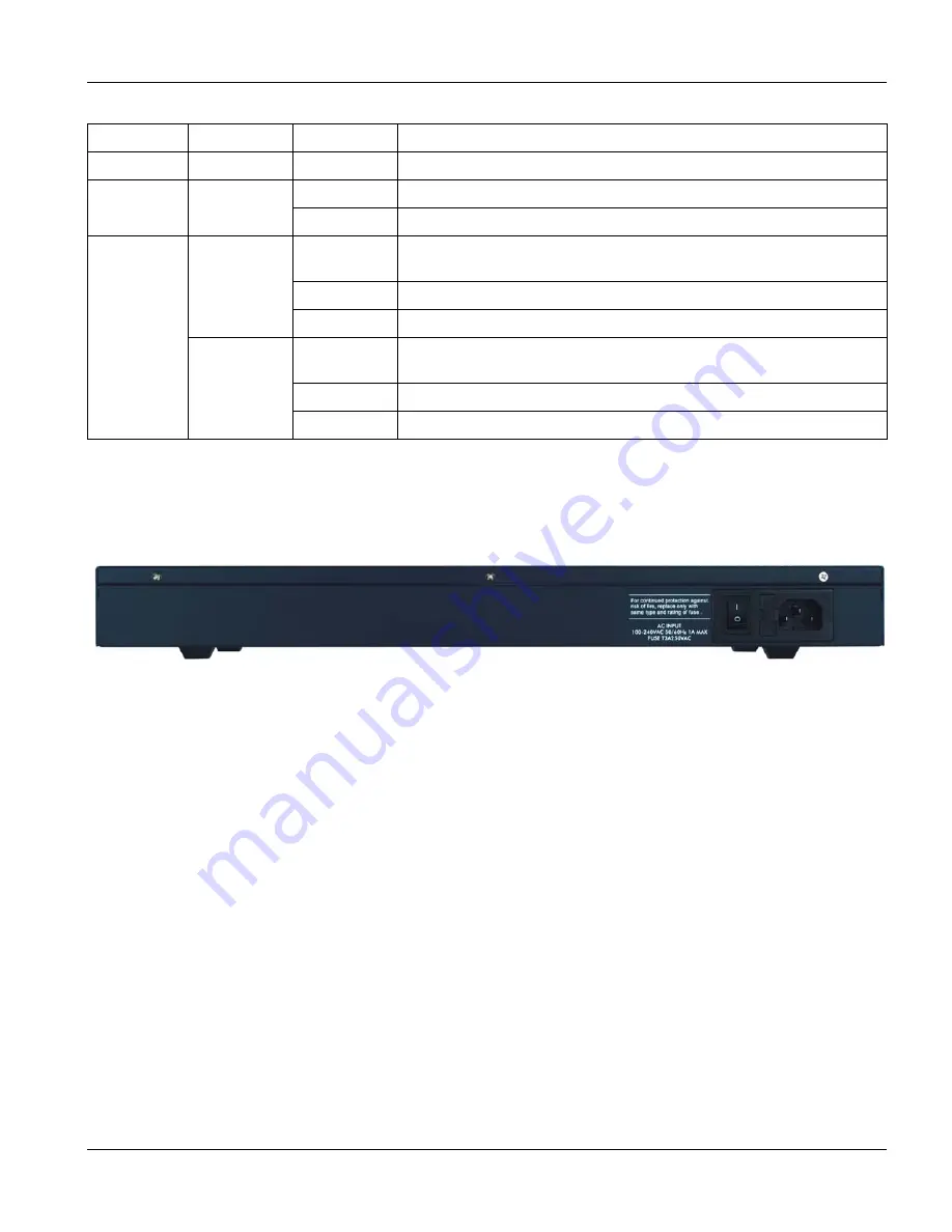
The following figure shows the rear panel of the VES. The rear panel contains the power receptacle and the power
switch.
Figure 3-2 VES-1124 Back Panel
3.3.1 Power
Connector
Make sure you are using the correct power source.
To connect the VES, plug the female end of the power cord to the power receptacle on the rear panel. Connect the
other end of the cord to a power outlet. Make sure that no objects obstruct the airflow of the fans (located on the
side of the unit).
Summary of Contents for VES-1124 -
Page 1: ...VES 1124 24 port QAM 2 band VDSL Switch User s Guide July 2004 Version 3 50 LP 0 ...
Page 18: ......
Page 23: ...VES 1124 User s Guide Getting to know the VES 1124 1 5 Figure 1 2 Curbside Application ...
Page 24: ......
Page 30: ......
Page 32: ......
Page 70: ......
Page 72: ......
Page 81: ...VES 1124 User s Guide VLAN 7 9 VID1 Example Screen Figure 7 6 VID1 Example Screen ...
Page 83: ...VES 1124 User s Guide VLAN 7 11 Figure 7 7 Port Based VLAN Setup All Connected ...
Page 86: ......
Page 98: ......
Page 100: ......
Page 104: ......
Page 116: ......
Page 124: ......
Page 128: ......
Page 130: ......
Page 134: ......
Page 154: ......
Page 170: ......
Page 188: ......
Page 190: ......
Page 194: ......
Page 198: ......


