background image

Copyright(C)2012ZeroUAV

All Rights Reserved

57

Appendix4

Appendix4

Appendix4

Appendix4

Configurate

Configurate

Configurate

Configurate WIFI

WIFI

WIFI

WIFI with

with

with

with N

N

N

N to

to

to

to WIFI

WIFI

WIFI

WIFI without

without

without

without N

N

N

N

Warning: Please read the instructions below carefully and severely modify the

configuration step by step.

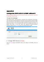
1 Login the webpage

When WIFI module, whose serial No. comes with "N",is powered on and works,

a AP with name of YS-X6-Serial No.N (Example:YS-X6-12345.N) will be builded.

Users can connect net AP with PC, and type in password:12345. Then open the

browser and type in the IP Add.192.168.1.254, the webpage will shown as

below, then

type

in the

user

name

and

password

(Username:admin

password:admin),click

Login

to enter the module allocation page.

2

Change DHCP Client to

Disable

Click on

“Basic”

page to find DHCP Client, and change it to Disable, shown as

below:

Summary of Contents for YS-X6

Page 1: ...C 2012ZeroUAV All Rights Reserved 1 YS X6 YS X6 YS X6 YS X6 Multi Rotor Multi Rotor Multi Rotor Multi Rotor Autopilot Autopilot Autopilot Autopilot Quick Start Guide Revised on October 22th 2012 www z...

Page 2: ...ht starts to blink in red for three times continuously indicating the connection is correct and motivated successfully The above the light blinks in red for three times is a sign to check whether all...

Page 3: ...are rich eletric current in the batterywire which can produce magnetic field users must place the batterywire far away from GPS and magnetic sensor module otherwise the craft will fly in circle in GPS...

Page 4: ...grated with router function and works in point to point If the serial number has no N then the WIFI module is ordinary without router function Serial number of YS X6 with N work in point to point show...

Page 5: ...up on the phone in same way IP should be 192 168 1 1 The indicator light on WIFI will be going on in blue if the WIFI module successfully connected to AP Then enable the WLAN on Phone Tablet to conne...

Page 6: ...elow 1 Channel Calibration 2 Check CH5 CH6 set up F S Fails safe 3 ESC stroke calibration This step is no need for special ESCs such as XA 4 Set up aircraft type and parameters Fill in local magnetic...

Page 7: ...position is 40 example the max left servo displays as left40 the mini throttle displays as 7 and the max as 90 It s correct if the actual servo operation is the same as Manual servo position showing o...

Page 8: ...means attitude is good if the light is off it means the attitude is too big After completing 2 3 laps horizontal rotation then go to the next step S S S STEP TEP TEP TEP2 2 2 2 Calibration Calibratio...

Page 9: ...to standard round then indicates a successful calibration and data in good condition Two round circles will show whether the calibration was successful or not If two round circles show up in the Cont...

Page 10: ...itched through CH5 Manual Manual Altitude Holding GPS Note the flight status on data page in GCS display manual manual auto hover CH6 can work only when CH5 stays at position 3 namely GPS mode CH6 is...

Page 11: ...cross indicating Mobile RC status has been off RC Status CH5 Status Mobile RC Status CH6 Status Craft Status Priority RC off X Auto Ena ble X When controlling by mobile there is a round circle showin...

Page 12: ...position 3 Auto return home landing mode Remark X X X X means irrelevant any kind of status When mobile remote control is enabled there is a round circle showing on the cross When Mobile transmitter i...

Page 13: ...ized parameters can be setup by customers to allocate motor mix control And the proportion coefficient of pitch toll and turning of each motor also can be customized for applying to the irregular Mult...

Page 14: ...ncrease to 100 Customized Customized Customized Customized toll toll toll toll parameters parameters parameters parameters to make the aircraft roll to right the changing method of corresponding motor...

Page 15: ...Disarm motors and Failsafe Enable Enable Enable Enable Motors Motors Motors Motors Protection Protection Protection Protection Any time after landing or before take off only if it is in manual mode a...

Page 16: ...at s more the throttle stick must be in the minimum 2 when mobile selects RC off click on motor off on mobile RC interface Or enable the receiver RC on according to the method 1 3 After auto returning...

Page 17: ...ing home instead of hovering Continue to return home and land if the signal is not recovered again RC RC RC RC receiver receiver receiver receiver Signal Signal Signal Signal Lost Lost Lost Lost Users...

Page 18: ...ed Keep still Position Hold DO NOT touch any area Position hold Operation 1 Press the circle and move up down 2 Press the circle and move left right 3 Press the circle and move left top left bottom ri...

Page 19: ...terface will be changed to a blue cross which indicates mobile attitude control mode has been enabled Notice Keep the phone in horizon before enabling attitude mode otherwise the craft will lean to th...

Page 20: ...1 Mobile phone tilt to front back 2 Mobile phone tilt to left right 3Mobile phone tilt to upleft downleft upright downright 1front back 2left right 3upleft downleft upright downr ight move Climb Desc...

Page 21: ...able flight it is normal when the vibrate state and shake state range from 0 9 the smaller the number the smaller the shaking the number will directly affect flying performance Tips Vibrating coeffici...

Page 22: ...otation torque automatically namely the differential make the clockwise rotation speed faster and anticlockwise slower In this condition aircraft can fly normally and do not need hover any more but th...

Page 23: ...sition Notice If there are any accidents during take off you can switch to manual mode by transmitter to control the craft C C C C Auto returning Auto returning Auto returning Auto returning home home...

Page 24: ...smile will change to purple star smile The operation of flying to the next position is same as above Remark Within 10 meters craft moves in level and beyond 10 meters the head of craft faces the targe...

Page 25: ...RC mode on phone Remark1 When left aileron outputs in RC interface the aircraft will hover clockwise around the target point When the right aileron outputs it will hover anti clockwise Remark2 Pushing...

Page 26: ...ed Speed Speed means the flying speed that craft flies to the next waypoint from present position Step2 Step2 Step2 Step2 After the waypoints design is completed it can be saved as file which can be u...

Page 27: ...Intelligent course locked in Setting page of GCS At that time the Intelligent course locked doesn t present care free function it presents free course mode That is craft will fly according to waypoint...

Page 28: ...tion of craft nose Option 2 Within 5 seconds please switch between position1 and position2 on CH6 for five times do not switch to position3 which is invalid that is 1 2 1 2 1 2 1 2 1 2 1 then FC will...

Page 29: ...ctory defaults The meaning of other parameters are as below Cell Cell Cell Cell Num Num Num Num The autopilot can calculate the low voltage alert according to the Cell Number filled in by users When t...

Page 30: ...Sensitivity PTZ PTZ PTZ PTZ Pitch Pitch Pitch Pitch Sensitivity Sensitivity Sensitivity Sensitivity EXT1 is the PTZ roll output and EXT2 is the PTZ pitch output Roll Pitch sensitivity is used to adjus...

Page 31: ...the comfortable level of THR in manual mode and without holding altitude Max Speed Setup of maximum flying speed Motor arming Setup of whether to use motor arming to remove throttle protection Protect...

Page 32: ...onnect to Receiver CH2 S BUS Only connect AP CH7 to the Receiver S BUS port PPM PPM is supported only connect AP CH8 to Receiver PPM Volt Volt Volt Volt Alert Alert Alert Alert Threshold Threshold Thr...

Page 33: ...irectly observe the present discharge current and battery consumption in data page of GCS If to use this function user must first connect power management module with YS X6 connect to A1N1 plug on YS...

Page 34: ...and can be interchanged 1 1 1 1 Data Data Data Data link link link link on on on on Craft Craft Craft Craft connection connection connection connection Take off WIFI module from craft and install dat...

Page 35: ...Notice If WIFI module works in point to point there is no need using router Data link and WIFI both are powered on by 3 S 6 S lithium battery same as AP MC the power cable is in red black two colours...

Page 36: ...d joystick WIFI Notice The WIFI here coming with joystick is different from the WIFI above in Part12 they can not be exchanged 1 Joystick Connection The joystick connection is quite simple just need t...

Page 37: ...ss operation please disable remote control on phone GCS to cancel the round circle on the cross 2 When RC is off the round circles on remote control cross interfaceof phone GCS will display once autom...

Page 38: ...acy of Multi rotor attitude adjustment User need to adjust weight and pitch of propeller to be proper so that motors can rotate in enough speed and generate enough servo effect For the craft seeking f...

Page 39: ...orrection of low speed craft 80 is default Without the compensation since the servo effect of low speed craft bigger propellers is too small when sticks on transmitter back to neutral position the cra...

Page 40: ...and COM1 for upgrade Wrong connection will lead upgrade failure Upgrade Upgrade Upgrade Upgrade Steps Steps Steps Steps Step1 Step1 Step1 Step1 Please do not power on FC and if FC is powered please di...

Page 41: ...n setting finished click on Open COM Step3 Step3 Step3 Step3 Click on Open button Select a arm file offered by Zero UAV to upgrade shown as below diagram Step4 Step4 Step4 Step4 Repower on the FC and...

Page 42: ...repower on AP the software doesn t auto upgrade please disable the software and replug the USB cable 2 If the below warning is showing when you choose firmware versions Please redownload the upgrade f...

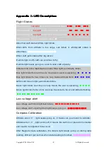
Page 43: ...ly Altitude hold in the Stabilization mode Blue light periodically blinks Blue light blinks for one time one loop means users is operating Blue light blinks for two times one loop means Altitude hold...

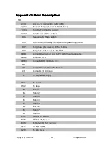
Page 44: ...Auto Hover Auto waypoints Returning Landing Switch CH7 For gimbal pitch servo Or for S BUS CH8 For gimbal roll servo Or for PPM COM1 Connect RS232 port and to PC for firmware upgrades COM2 Extended po...

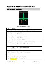
Page 45: ...aircraft 2 Data Real time flight data 3 Map Real time map or saved map 4 Settings Setup various states of craft 5 Parameters Adjust craft parameters 6 Cross Interface General control the flight 7 The...

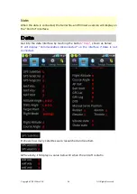
Page 46: ...on the Control interface Data Data Data Data Get into the data interface by touching the button Data shown as below It will display Communication disconnected on the interface if data is not connected...

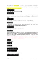
Page 47: ...r which you want the aircraft fly to It displays the craft states Manual Manual Altitude Hold Auto Hover Auto Navigation Auto Go Home and Land setup status Barometer altitude of the craft unit is mete...

Page 48: ...mitter Settings Vibrations from IMU 1 10 means your aircraft is in good condition 10 above it means vibration exceeds limits Up down is the vertical vibrate and front back left right is the horizon vi...

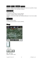
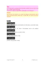
Page 49: ...ed map when network is on enable the software to download the map If finishing downloading the cached map if enable WIFI the cached map will be displayed Locate Locate Locate Locate After the GPS was...

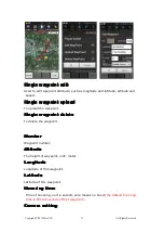
Page 50: ...Target Lock Fly page Click it to enter editing waypoints please check Waypoints Fly Page Locate FlytoPP PTZLock Move Map center to operation area Exit FlytoPP PTZLock Remove the FlytoPP PTZLock mode...

Page 51: ...waypoint waypoint waypoint waypoint delete delete delete delete To delete the waypoint Number Number Number Number Waypoint number Altitude Altitude Altitude Altitude The height of waypoint unit meter...

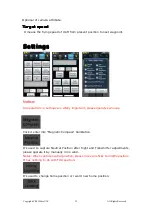
Page 52: ...ings Notice All operations in settings are vitally important please operate seriously Click it enter into Magnetic Compass Calibration It s used to capture Neutral Position after flight and Transmitte...

Page 53: ...te Generally phone position has error about 5 10 meters In Auto Navigation mode fill in the new waypoint number which you will fly to Attention Fill in a number which is in the range of uploaded waypo...

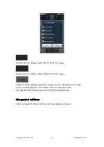
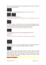
Page 54: ...lays 7 Pushing to the Maximum it displays 90 It s used to align channels or complete parameters of craft After clicking this button flight state will display Settings After getting into settings the c...

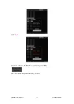
Page 55: ...Copyright C 2012ZeroUAV All Rights Reserved 55 click Get Users can observe the functions opened in yourself FC User can define the parameters by yourself...

Page 56: ...called mix control The ratio of mix output is up to the mechanical structure of craft User can configurate the output coefficient of motors to make the fix control realized Please refer to the Part 6...

Page 57: ...y step 1 Login the webpage When WIFI module whose serial No comes with N is powered on and works a AP with name of YS X6 Serial No N Example YS X6 12345 N will be builded Users can connect net AP with...

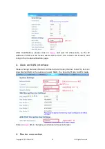
Page 58: ...be locked as192 168 1 254 Then refresh the browser and relogin the module allocation page 3 Click on WIFI interface Please change Network Mode to Infrastructure mode Channel to AUTO Service Area Name...

Page 59: ...ype in password 12345678 Type in 192 168 1 254 in the browser it indicates the modification is successful if you can login the back interface of WIFI After power on the AP user can enable the phone GC...

Page 60: ...Copyright C 2012ZeroUAV All Rights Reserved 60...

Reviews: