


SM-18001
SERVICE MANUAL
INVERTER-DRIVEN MULTI-SPLIT SYSTEM
HEAT PUMP AIR CONDITIONERS
Service Manual
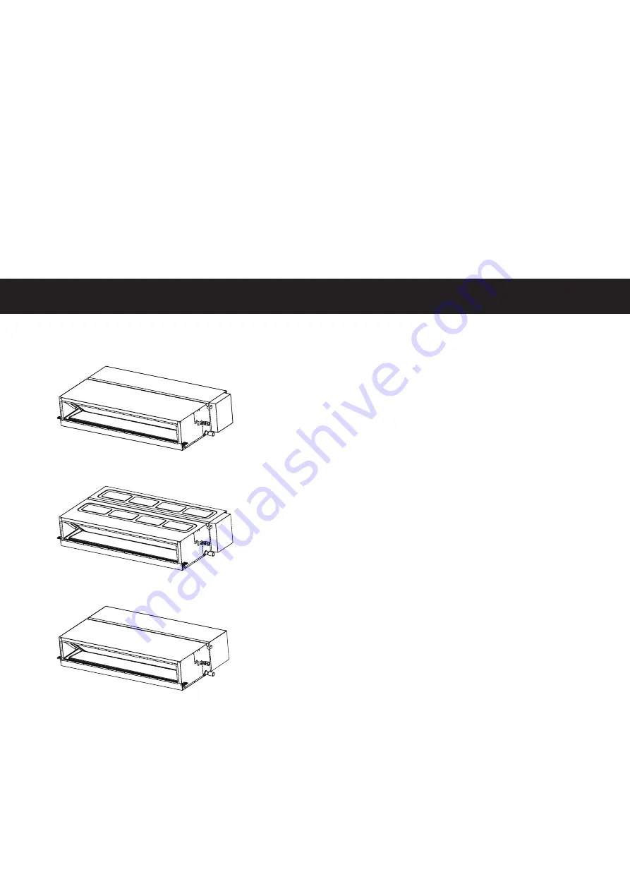
< Indoor Units >
● Ducted (High Static) Type
(H,Y)IDH018B21S
(H,Y)IDH024B21S
(H,Y)IDH030B21S
(H,Y)IDH036B21S
(H,Y)IDH048B21S
● Ducted (Medium Static) Type
(H,Y,C)IDM006B21S
(H,Y,C)IDM008B21S
(H,Y,C)IDM012B21S
(H,Y,C)IDM015B21S
(H,Y,C)IDM018B21S
(H,Y,C)IDM024B21S
(H,Y,C)IDM030B21S
(H,Y,C)IDM036B21S
(H,Y,C)IDM048B21S
● Ducted (Slim) Type
(H,Y,C)IDS006B21S
(H,Y,C)IDS008B21S
(H,Y,C)IDS012B21S
(H,Y,C)IDS015B21S
(H,Y,C)IDS018B21S
Summary of Contents for CIDH018B21S
Page 2: ......
Page 10: ...viii SM 18001 rev 1...
Page 15: ...SM 18001 rev 1 1 1 INSTALLATION 1 Installation...
Page 19: ...SM 18001 rev 1 2 1 OPERATION 2 Operation...
Page 22: ......
Page 23: ...SM 18001 rev 1 3 1 TROUBLESHOOTING 3 Troubleshooting...
Page 75: ...MAINTENANCE SM 18001 rev 1 4 1 4 Maintenance...
Page 130: ......
Page 172: ......
Page 173: ...SM 18001 rev 1 6 1 FIELD WORK INSTRUCTIONS 6 Field Work Instructions...
Page 182: ...6 10 SM 18001 rev 1 FIELD WORK INSTRUCTIONS 6 8 Mollier Chart for R410A f t 3 l b...
Page 183: ...SERVICE PARTS LIST SM 18001 rev 1 7 1 7 Service Parts List...
Page 185: ......
Page 186: ...2018 Johnson Controls Inc SM 18001 rev 1 Code No LIT 12013047 Revised February 2019...


