41
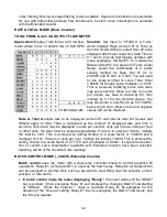
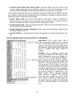
The zero index channel has the same digital filtering as the A & B channels. It contains a
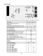
Polarity jumper that allows selection of either a positive or negative zero index signal. It also
contains two Control inputs, C1 and C2 that control the ANDing of the zero index signal with
the Channel A and Channel B signals. See “Zero Index Setup” below.
The Item indicator light (center right) may be used to determine the location of the Zero
Index. This indicator is lighted while the zero index signal is being received. The zero index
signal must be jumpered for the correct polarity. If, during encoder motion, the indicator is
on more than it is off, it is likely that the zero index signal is jumpered for the wrong polarity.
If so, add a Polarity jumper to switch E8, position C. If it already has a jumper, remove it.
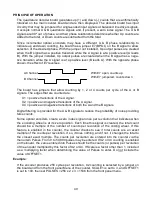
From the menu, a value may be entered for Offset1. As explained below under “Mechanical
Zero”, OFFSET1 allows a mechanical zero position different from the zero index position.
The displayed value is the sum of the following:
1.
The total bidirectional counts from the optical encoder since the last counter reset or
function reset.
2.
The correction factor from the last zero index correction calculation.
3.
OFFSET1
Example:
Suppose that the encoder contains 30 pulses per revolution and that X1 counting is used.
Further suppose that when the mechanics are at their 0 position, the zero index is at 10,
OFFSET 1 = 10, and the counter is reset when the encoder is at the 5 position.
Reset
v
Position
0
5
10
20
30
40
50
Index
^
^
Internal Total
0
5
15
25
35
45
Correction
0
-5
-5
-5
-5
-5
OFFSET
10
10
10
10
10
10
-----
----
----
----
----
----
Display
10
10
20
30
40
50
Internal Total
-5
0
5
15
25
35
45
Correction
-5
-5
-5
-5
-5
-5
-5
OFFSET
10
10
10
10
10
10
10
----
----
----
----
----
----
----
Display
0
5
10
20
30
40
50
Once the index point has been passed, the display matches the position. Prior to that, the
display is in error.
When the counter is displaying Quadrature Total and the Total is reset using the Reset &
Peak buttons (Function Reset), the internal Total is set to zero, but the zero index correction
is not affected. This results in a display of the correction value plus OFFSET1. To zero the
internal Total and the correction value, the counter must be reset using the Reset & Menu
buttons (Meter Reset). This results in a display of OFFSET1.
Summary of Contents for 800 plus
Page 63: ...63 SERIAL CONNECTION EXAMPLES ...


