17
DISPLAY TOTAL VOLUME BY ADDING TWO TURBINE FLOW METER CHANNELS
Application:
Display total liquid volume in
gallons to two decimal places from 2 pipes
dispensing liquids into the same tank. Flow
meter A is calibrated to 36.67 pulses/gal-
lon, flow meter B to 58.12 pulses/gallon.
Solution:
Arithmetic operations require the
Extended counter. Apply flow meter output
A output to Channel A, flow meter output B
to Channel B. Set Input to “Total A+B.” Set
Gate Time to 0.01 sec for fast display up-
dates. Select a positive trigger slope for A
and B. Set DecPt2, which applies to Grand
Total, and DecPt1, which applies to Totals
A and B, both to two decimal places. Under
Setup, select the coordinates of 2 points
scaling method for A and B. To scale A,
enter 36.67 (pulses) for Hi In1 and 1.00
(gallons) for Hi Rd1. To scale B, enter
58.12 (pulses) for Hi In2 and 1.00 (gallons)
for Hi Rd2. The normal display will be Item
#1 (Grand Total). Press the key to view
Item #2 (Total A) and Item #3 (Total B).
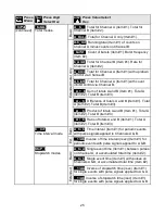
TOTAL A ONLY (A
_
OnLy)
displays the number of pulses applied to Channel A as Item #1. If
scientific notation is not selected, overflows beyond 999,999 are recorded in units of 1,000,000
as Item #2. For example, a total of 17,345,676 would be displayed as 345,675 in Item #1 and
17 in Item #2. This capability gives the counter 12-digit capability. Items #1-2 can also be
retrieved via serial communications.
•
TOTAL A B (A
__
b
__
)
displays Total A as Item #1 or Total B as Item #2.
•
TOTALS A+B
,
A-B
,
AxB
,
A-B, A/B
(Extended counter) display arithmetic combinations
of Totals A and B as Item #1, Total A as Item #2, and Total B as Item #3.
•
TOTAL A-B UD (A-b
_
Ud)
is the same as TOTAL A-B, except that counts are subtracted
on an ongoing basis, instead of subtracting totals. This avoids round-off errors with large
totals. Overflows are displayed as #2. (See Total A only)
•
BURST (
_
burST)
(Extended counter) displays the total number of signal bursts applied
to Channel B as Item #1. Gate time must be greater than the period of the lowest signal
frequency and less than the minimum time between bursts. Time-out should be set to 0.
•
TOTAL A B U/D (A
_
bU/d)
(Extended counter) displays Total A as Item #1, where the up
or down count direction is determined by an input on Channel B. If the menu item
SLOPE
is set to 0 for Channel B, (digit 6), an input level on B below the jumper set Low
Threshold B causes the count to go up, and an input level above the jumper set High
Threshold causes the count to go down. If
SLOPE
for Channel B is set to 1, the opposite
occurs. The maximum frequency on A that can be counted is 250 kHz, or a minimum of 4
µs between pulses.
Summary of Contents for 800 plus
Page 63: ...63 SERIAL CONNECTION EXAMPLES ...


