


20
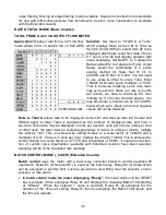
STOPWATCH TIMING, CLOSING TIME OF A RELAY TO 0.001 MSEC RESOLUTION
Application:
Measure the closing time of a
relay in msec to 0.001 msec resolution.
Solution:
To close the relay, apply the
same positive voltage to the relay coil and
to meter Channel A. Wire the relay so that
0V is applied across Channel B when the
contacts are closed. Set Input to “Stop-
watch A to B.” Select a positive trigger
slope for A and a negative trigger slope for
B. Under Config, set Display Mode to sec.
Set Gate Time to 0.01 sec. Select the
coordinates of 2 points scaling method for
Item #1. Set DecPt1 to 3 places. Set Hi In1
to 1.00000 (sec) and Hi Rd1 to 999.999
(msec). Ignore Item #2, which is not used.
•
TIME INTERVAL A TO B (A
_
to
_
b)
measures time between periodic inputs on Channels
A and B. Timing starts when a pulse is applied to Channel A (positive edge if slope A is 0,
negative edge if slope A is 1), and ends when a pulse is applied to Channel B (positive
edge if slope B is 0, negative edge if slope B is 1). Pulse width may be measured by tying
inputs A and B together and selecting a positive or negative edge to start (Slope A) and
the opposite polarity edge to stop (Slope B). If multiple start and stop pulses occur during
the
gate time
, the displayed value is the average of pulse widths. The value is updated at
the end of each
gate time
. With a scale factor of 1, one count is one microsecond.
•
INVERSE TIME INTERVAL (
__
1/Ab)
(Extended counter)
Takes the inverse of time interval for a reading in /second. For example, if the average
time interval for object to travel from point A to point B is 5 seconds, the inverse time
interval would be 0.2/sec. For the average speed of the objects, simply apply a scale
factor equal to the distance separating the two points, such as 7 (inches). Speed would
then be displayed as 7 x 0.2 = 1.4 (inches/sec). For a 6-digit reading, apply a scale
multiplier of 10,000 and move the decimal point.
•
STOPWATCH A TO A (A
_
to
_
A)
measures time between the same positive (or negative)
edge of start and stop pulses applied to Channel A. Single event times may be displayed
as Item #1 in decimal seconds, minutes or hours, or in HH:MM:SS clock format. Time is
reset to 0 when a new start pulse occurs. Accumulated total time may be displayed as
Item #2. With a scale factor of 1, one count is one microsecond.
•
STOPWATCH A TO B
(A
_
to
_
B)
measures time between a start pulse on Channel A and
a stop pulse on Channel B. Timing is the same as for A to A, except that positive or
negative edges may be selected separately for Channels A and B. This allows the pulse
width measurement of single pulses by tying Channels A and B together. One slope is
selected to start timing, and the opposite slope to stop timing.
Summary of Contents for 800 plus
Page 63: ...63 SERIAL CONNECTION EXAMPLES ...