


9 Operation
9.3.2 Operating Procedure in Speed Control Mode (Pn000 = n.
0
)
9-24
9.3.2 Operating Procedure in Speed Control Mode (Pn000 = n.
0
)
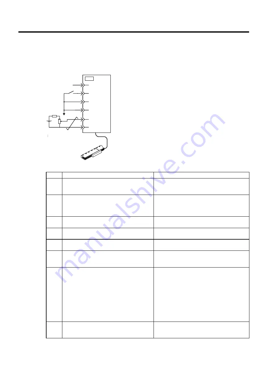
The following circuit is required: External input signal circuit or equivalent.
Step
Description
Check Method and Remarks
1
Check the power and input signal circuits again, and
check that the speed reference input (voltage
between the V-REF and SG) is 0 V.
Refer to the above figure for input signal circuit.
2
Turn ON the servo ON (/S-ON) input signal.
If the linear servomotor moves with the speed refer-
ence input 0V, refer to
9.7.3 Adjusting Offset
, and use
the reference voltage offset to keep the linear servomo-
tor from moving.
3
Generally increase the speed reference input voltage
between V-REF and SG from 0 V.
The factory setting is 6 V/rated speed.
4
Check the speed reference input to the
SERVOPACK (Un000 [mm/s]).
Refer to
8.1.3 Basic Mode Selection and Operation
for
how it is displayed.
5
Check the Un000 (motor speed [mm/s].
Refer to
8.1.3 Basic Mode Selection and Operation
for
how it is displayed.
6
Check that the Un001 and Un000 values in steps 4
and 5 are equal.
Change the speed reference input voltage and check
that Un001 and Un000 values are equal for multiple
speed references.
7
Check the speed reference input gain and motor
movement direction.
Refer to the following equation to change the Pn300
(speed reference input gain).
Un001=(voltage between V-REF) [V] × Pn300 [rated
speed/6V]
To change the motor movement direction without
changing polarity for speed reference input gain, refer
to
9.6.2 Switching the Linear Servomotor Movement
Direction
.
Perform the operation from step 2 again after the
motor rotation direction is changed.
8
When the speed reference input is set to 0 V and
servo OFF status enters, the trial operation for ser-
vomotor without load is completed.
−
47
CN1
+24V
/S-ON
P-OT
N-OT
V-REF
40
42
43
5
6
SERVOPACK
0V
V
E
V
E
Max. voltage 12V
+
−
Summary of Contents for SGLFW
Page 270: ...9 3 9...


