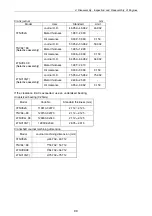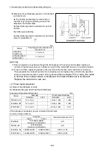
4. Disassembly, Inspection and Reassembly of Engines
101
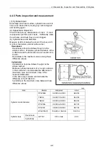
(4) Piston
Especially clean the combustion surface,
circumference, ring grooves and piston pin bosses,
and check after removing any carbon deposit. Any
burr at a ring groove or snap ring groove shall be
removed. If crack is suspected, inspect by color
check.
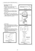
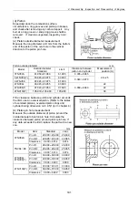
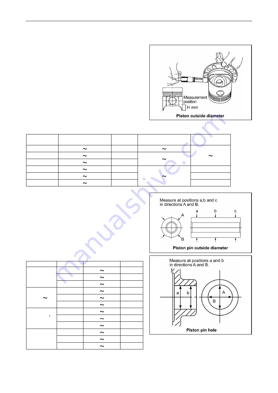
(a) Piston outside diameter measurement
Measure the long diameter at H mm from the bottom
end of the piston of the oval hole in the vertical
direction to the piston pin hole.
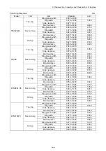
Piston outside diameter mm
Model
Outside diameter
Standard
Limit
Clearance between
piston and cylinder
Measurement
position (H)
3TNV82A 81.950 81.980 81.905 0.035 0.065
3,4TNV84(T) 83.945 83.975 83.900
3,4TNV88 87.945 87.975 87.900
0.040 0.070
22 25
4TNV94L 93.945 93.955 93.900
22
4TNV98(T) 97.940 97.950 97.895
22
4TNV106(T) 105.930 105.960 105.880
0.050 0.080
30
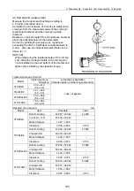
If the clearance between piston and cylinder exceeds
the limit, use an oversized piston. (Refer to the tables
of oversized pistons, oversized piston rings and
cylinder boring dimension on 4.4.5(1)(c) in chapter 4.)
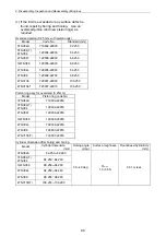
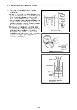
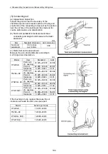
(b) Piston pin hole measurement
Measure the outside diameter of piston pin and the
inside diameter of piston pin hole. Calculate the
clearance between piston pin and piston pin hole. If
any data exceeds the limit, replace the part with a new
one.
mm
Model Item Standard Limit
Pin I.D.
23.000 23.009
23.039
Pin O.D.
22.995 23.000
22.965
3TNV82A
Clearance 0.000 0.014 0.074
Pin I.D.
26.000 26.009
26.039
Pin O.D.
25.995 26.000
25.965
TNV84 88
Clearance 0.000 0.014 0.074
Pin I.D.
30.000 30.009
30.039
Pin O.D.
29.989 30.000
29.959
4TNV94L
4TNV98(T)
Clearance 0.000 0.020 0.080
Pin I.D.
37.000 37.011
37.039
Pin O.D.
36.989 37.000
36.959
4TNV106(T)
Clearance 0.000 0.022 0.080
Summary of Contents for 3TNV Series
Page 1: ...4TNV106 4TNV106T 4TNV94L 4TNV98 4TNV98T 3TNV82A 3TNV84 T 4TNV84 T 3TNV88 4TNV88 ...
Page 31: ...1 General 1 4 Engine External Views 16 ...
Page 32: ...1 General 1 5 Structural Description 17 ...
Page 156: ...9 Starting Motor 9 1 2 Components 141 ...
Page 157: ...9 Starting Motor 9 1 3 Troubleshooting 142 ...
Page 172: ...9 Starting Motor 9 2 3 Troubleshooting 157 ...
Page 175: ...9 Starting Motor 2 Removal of magnetic switch Remove the M6 bolts 10mm 2 160 ...
Page 185: ...9 Starting Motor 3 Brush 1 Check wear of the brush and the brush spring force 170 ...
Page 194: ...10 Alternator 179 10 1 6 Troubleshooting ...
Page 195: ...11 Electric Wiring 180 11 ELECTRIC WIRING 11 1 Electric Wiring Diagram ...
Page 213: ......

