4. Disassembly, Inspection and Reassembly of Engines
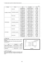
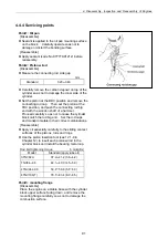
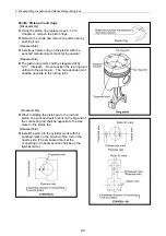
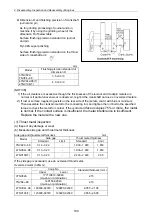
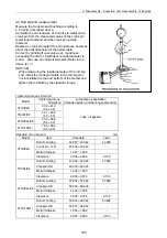
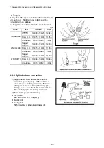
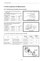
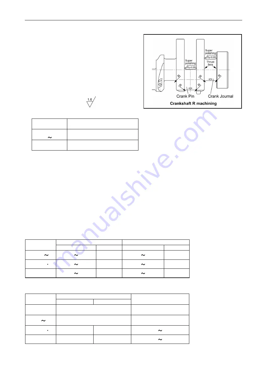
Dimension R and finishing precision of crankshaft
journal and pin
As for grinding processing of journal and pin,
machine it by using the grinding wheel of the
dimension R of below table.
Surface finishing precision standard on journal
and pin:
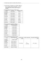
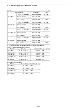
Code No.
Standard thickness (mm)
Ry=0.8S super polishing
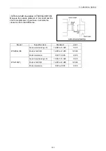
Surface finishing precision standard on the thrust
side of crankshaft arm:
Upper Lower
3TNV82A
???119810-02940
mm
Model
Finishing precision standard of
dimension R
(Up-down combination)
2.15
TNV84 88
3TNV82A
TNV84 88
3.5 +0.3/ 0
129150-02940
(Up-down combination)
2.15
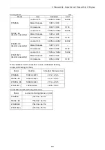
TNV82A 88 0.14 0.22 - 1.930 1.980 1.850
4TNV94L 98 0.13 0.23 -
4TNV106(T) 0.13 0.23 - 2.430 2.480 2.35
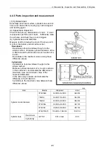
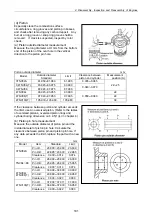
If the side gap is exceeded, use an oversized thrust metal.
Oversized metal (0.25mm)
4TNV94L/98(T)
4TNV94L 98 129900-02370
4TNV106(T)
4.0 +0.3/ 0
[NOTICE]
129900-02360
2.055 2.105
4TNV106(T)
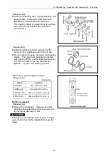
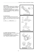
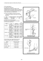
1) lf the oil clearance is excessive though the thicknesses of the iournal and crankpin metals are
normal or if partial uneven wear is observed, re-grind the crankshaft and use an oversized metals.
2)
lf rust or surface roughening exists on the rear side of the metals, coat it with blue or minimum.
Then assemble the crankpin metal to the connecting rod, and tighten the rod bolt to the specified
torque to check the metal for contact. lf the contact
surface occupies 75% or more, the metal
is normal. lf the contact surface is insufficient, the metal interference is insufficient.
Replace the metal with a new one.
123900-02370 123900-02360
2.555 2.605
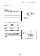
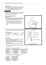
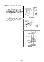
(1) Thrust metal inspection
(a) Inspect any damage or wear.
(b) Measure side gap and thrust metal thickness
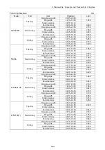
Side gap and thrust metal thickness mm
Side gap
Model
Thrust metal thickness
Standard Limit Standard Limit
1.930 1.980 1.850
-
100
Summary of Contents for 3TNV Series
Page 1: ...4TNV106 4TNV106T 4TNV94L 4TNV98 4TNV98T 3TNV82A 3TNV84 T 4TNV84 T 3TNV88 4TNV88 ...
Page 31: ...1 General 1 4 Engine External Views 16 ...
Page 32: ...1 General 1 5 Structural Description 17 ...
Page 156: ...9 Starting Motor 9 1 2 Components 141 ...
Page 157: ...9 Starting Motor 9 1 3 Troubleshooting 142 ...
Page 172: ...9 Starting Motor 9 2 3 Troubleshooting 157 ...
Page 175: ...9 Starting Motor 2 Removal of magnetic switch Remove the M6 bolts 10mm 2 160 ...
Page 185: ...9 Starting Motor 3 Brush 1 Check wear of the brush and the brush spring force 170 ...
Page 194: ...10 Alternator 179 10 1 6 Troubleshooting ...
Page 195: ...11 Electric Wiring 180 11 ELECTRIC WIRING 11 1 Electric Wiring Diagram ...
Page 213: ......

