5. LUBRICATION SYSTEM ........................................................................ 108
5.1 Lubrication System Diagram ............................................................................................... 108
5.2 Trochoid Pump Components ............................................................................................... 109
5.3 Disassembly(Reverse the procedure below for assembly) ................................................. 109
5.4 Servicing Points................................................................................................................... 109
5.5 Parts Inspection and Measurement......................................................................................110
5.5.1 Trochoid pump inspection and measurement.......................................................................110
6. COOLING SYSTEM.................................................................................112
6.1 Cooling Water System ..........................................................................................................112
6.2 Cooling Water Pump Components .......................................................................................112
6.3 Disassembly (Reverse the procedure below for assembly) .................................................113
6.4 Servicing Points....................................................................................................................113
7. FUEL INJECTION PUMP/GOVERNOR...................................................114
7.1
Introduction ...........................................................................................................................114
7.2 Fuel Injection Pump..............................................................................................................114
7.2.1 Fuel system diagram ............................................................................................................114
7.2.2 External view and components.............................................................................................115
7.2.3 Disassembly procedure:.......................................................................................................115
7.2.4 Assembly procedure.............................................................................................................116
7.2.5 Servicing points ....................................................................................................................116
8. TURBOCHAGER: Disassembly, inspection and reassembly.....................118
8.1 Structure and Functions........................................................................................................118
8.1.1 Main specifications ...............................................................................................................118
8.1.2 Construction .........................................................................................................................118
8.1.3 Structural and functional outline ...........................................................................................119
8.1.4 Components .........................................................................................................................120
8.2 Service Standards and Tightening Torque........................................................................... 121
8.2.1 Service standards.................................................................................................................121
8.2.2 Tightening torque..................................................................................................................122
8.3 Periodic Inspection Procedure............................................................................................. 123
8.3.1 Periodic inspection intervals .................................................................................................123
8.3.2 Inspection procedure............................................................................................................124
8.3.3 Waste gate valve adjustment procedure ..............................................................................125
8.4 Disassembly Procedure....................................................................................................... 127
8.4.1 Preparation for disassembly.................................................................................................127
8.4.2 Inspection before disassembly .............................................................................................128
8.4.3 Disassembly.........................................................................................................................128
Summary of Contents for 3TNV Series
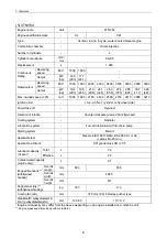
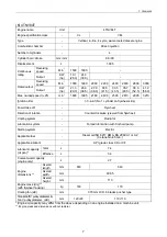
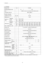
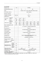
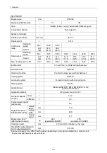
Page 1: ...4TNV106 4TNV106T 4TNV94L 4TNV98 4TNV98T 3TNV82A 3TNV84 T 4TNV84 T 3TNV88 4TNV88 ...
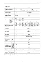
Page 31: ...1 General 1 4 Engine External Views 16 ...
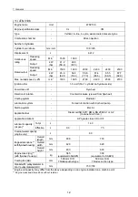
Page 32: ...1 General 1 5 Structural Description 17 ...
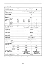
Page 156: ...9 Starting Motor 9 1 2 Components 141 ...
Page 157: ...9 Starting Motor 9 1 3 Troubleshooting 142 ...
Page 172: ...9 Starting Motor 9 2 3 Troubleshooting 157 ...
Page 175: ...9 Starting Motor 2 Removal of magnetic switch Remove the M6 bolts 10mm 2 160 ...
Page 185: ...9 Starting Motor 3 Brush 1 Check wear of the brush and the brush spring force 170 ...
Page 194: ...10 Alternator 179 10 1 6 Troubleshooting ...
Page 195: ...11 Electric Wiring 180 11 ELECTRIC WIRING 11 1 Electric Wiring Diagram ...
Page 213: ......


