4. Disassembly, Inspection and Reassembly of Engines
[Reassemble]
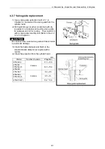
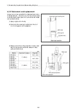
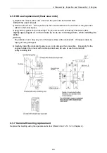
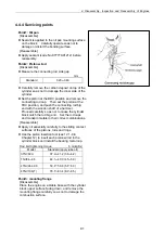
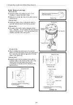
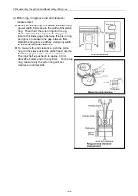
Apply sealant (code No.977770-01212) and install
the mounting flange by matching the two dowel
pins. After assembly, raise the engine with its
mounting flange on the bottom side.
Unforeseen injury may arise due to falling of slipping
when raising or reversing the engine. Carefully
operate so as not to lose balance.
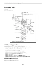
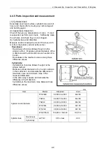
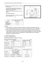
Point4: Journal bearing cap
[Disassemble]
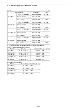
4TNV106(T) 36.250 36.275
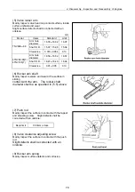
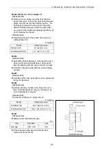
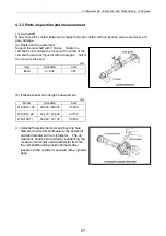
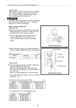
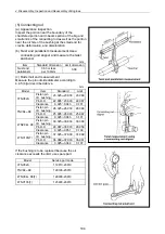
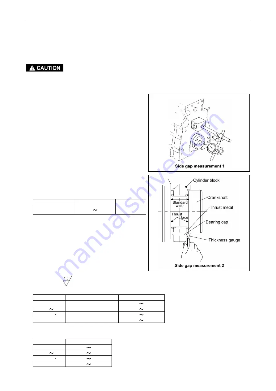
Before removing the journal bearing, measure the
crankshaft side gap. Measure it in either method
because there are the next two methods.
1) Install a dial gage on the cylinder block, and
move a crankshaft in front and back, and
measure the side gap as shown in the right
figure.
2) Put a thickness gauge in the clearance between
thrust metal and crankshaft directly, and measure
it.
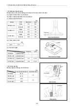
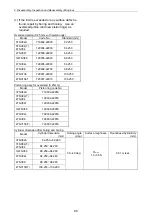
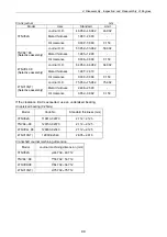
Side gap standard mm
Model Standard
Limit
All models
0.13 0.23
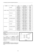
The standard width of the crankshaft thrust part
mm
Model Standard
thickness
3TNV82A 25.250 25.271
TNV84 88 28.250 28.271
0.28
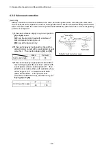
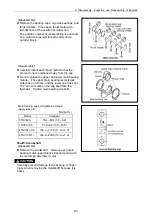
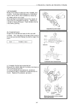
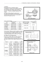
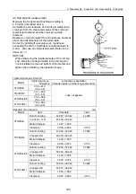
[Reassemble]
If the side gap exceeds the standard, replace the
thrust metal with an oversize one.
Machine the standard width of the crankshaft
thrust part into the dimension of the below table at
the same time.
Refer to a parts catalog when ordering the part.
The surface finishing precision (refer to 4.4.5(2) in
Chapter4):
0.25mm Oversized thrust metal (0.25DS) mm
0.25DS
Thrust metal assy code
Standard thickness
3TNV82A 119810-02940 2.055 2.105
TNV84 88 129150-02940 2.055 2.105
4TNV94L 98 129900-02940
2.055 2.105
4TNV106(T) 123900-02940 2.555 2.605
32.250 32.275
4TNV94L 98
92
Summary of Contents for 3TNV Series
Page 1: ...4TNV106 4TNV106T 4TNV94L 4TNV98 4TNV98T 3TNV82A 3TNV84 T 4TNV84 T 3TNV88 4TNV88 ...
Page 31: ...1 General 1 4 Engine External Views 16 ...
Page 32: ...1 General 1 5 Structural Description 17 ...
Page 156: ...9 Starting Motor 9 1 2 Components 141 ...
Page 157: ...9 Starting Motor 9 1 3 Troubleshooting 142 ...
Page 172: ...9 Starting Motor 9 2 3 Troubleshooting 157 ...
Page 175: ...9 Starting Motor 2 Removal of magnetic switch Remove the M6 bolts 10mm 2 160 ...
Page 185: ...9 Starting Motor 3 Brush 1 Check wear of the brush and the brush spring force 170 ...
Page 194: ...10 Alternator 179 10 1 6 Troubleshooting ...
Page 195: ...11 Electric Wiring 180 11 ELECTRIC WIRING 11 1 Electric Wiring Diagram ...
Page 213: ......


