7-23
S
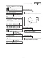
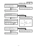
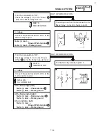
Start the engine and accelerate to about
5,000 r / min.
OUT OF
SPECIFICATION
MEETS SPECIFICATION
NOTE:
Charging voltage:
14 V at 5,000 r / min
Use a fully charged battery.
EB804012
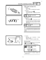
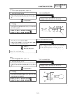
4. Stator coil resistance
S
Disconnect the AC magneto coupler from
the wire harness.
S
Connect the pocket tester (
Ω
1) to the sta-
tor coils.
S
Measure the stator coil resistance.
Replace the stator coil assembly.
OUT OF SPECIFICATION
Tester (+) lead
White terminal
Tester (–) lead
White terminal
Stator coil resistance:
0.50
X
0.62
Ω
at 20
_
C
BOTH MEET
SPECIFICATION
EB804015
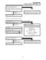
5. Wiring connections
S
Check the connections of the entire charg-
ing system.
Refer to “CIRCUIT DIAGRAM”.
POOR CONNECTION
CORRECT
Properly connect the charging system.
Replace the rectifier / regulator.
Tester (+) lead
White terminal
Tester (–) lead
White terminal
The charging circuit is not faulty.
1
2
3
1
CHARGING SYSTEM
ELEC
Summary of Contents for XVS6501997
Page 1: ......
Page 2: ......
Page 8: ......
Page 10: ...GEN INFO ...
Page 18: ...GEN INFO ...
Page 20: ...SPEC ...
Page 44: ...2 24 LUBRICATION DIAGRAMS SPEC 1 Crankshaft 2 Oil filter 3 Oil pump ...
Page 102: ...INSP ADJ ...
Page 188: ...CARB ...
Page 198: ...CARB ...
Page 266: ...CHAS ...
Page 268: ...ELEC SELF DIAGNOSIS 7 49 TROUBLESHOOTING 7 50 ...
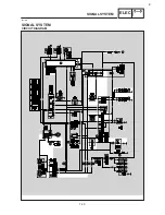
Page 298: ...E 7 30 SIGNAL SYSTEM ELEC EB806000 SIGNAL SYSTEM CIRCUIT DIAGRAM ...
Page 320: ...TRBL SHTG ...
Page 326: ...TRBL SHTG ...


