4-24
b
VALVES AND VALVE SPRINGS
ENG
NOTE:
*****************************************************
*****************************************************
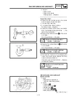
5. Measure:
S
Runout (valve stem)
Out of specification
Replace.
Runout limit:
0.03 mm
D
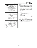
When installing a new valve always replace
the guide.
D
If the valve is removed or replaced always re-
place the oil seal.
6. Eliminate:
S
Carbon deposits
(from the valve face and valve seat)
7. Inspect:
S
Valve seats
Pitting/ wear
Reface the valve seat.
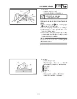
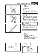
8. Measure:
S
Valve seat width
a
Out of specification
Reface the valve
seat.
Valve seat width:
Intake:
1.0
1.2 mm
<Limit>:
1.8 mm
Exhaust:
1.0
1.2 mm
<Limit>:
1.8 mm
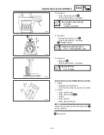
Measurement steps:
D
Apply Mechanic’s blueing dye (Dykem)
b
to
the valve face.
D
Install the valve into the cylinder head.
D
Press the valve through the valve guide and
onto the valve seat to make a clear pattern.
D
Measure the valve seat width. Where the
valve seat and valve face made contact,
blueing will have been removed.
D
If the valve seat is too wide, too narrow, or the
seat is not centered, the valve seat must be
refaced.
Summary of Contents for XVS6501997
Page 1: ......
Page 2: ......
Page 8: ......
Page 10: ...GEN INFO ...
Page 18: ...GEN INFO ...
Page 20: ...SPEC ...
Page 44: ...2 24 LUBRICATION DIAGRAMS SPEC 1 Crankshaft 2 Oil filter 3 Oil pump ...
Page 102: ...INSP ADJ ...
Page 188: ...CARB ...
Page 198: ...CARB ...
Page 266: ...CHAS ...
Page 268: ...ELEC SELF DIAGNOSIS 7 49 TROUBLESHOOTING 7 50 ...
Page 298: ...E 7 30 SIGNAL SYSTEM ELEC EB806000 SIGNAL SYSTEM CIRCUIT DIAGRAM ...
Page 320: ...TRBL SHTG ...
Page 326: ...TRBL SHTG ...

