4-40
CLUTCH
ENG
70 Nm (7.0 m
kg)
NOTE:
70 Nm (7.0 m
kg)
NOTE:
*****************************************************
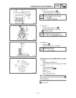
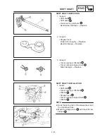
PUSH ROD INSPECTION
1. Inspect:
Push rod #1
1
O-ring
Ball
2
Push rod #2
3
Cracks / wear / damage
Replace.
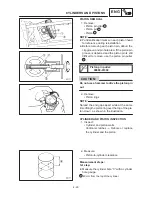
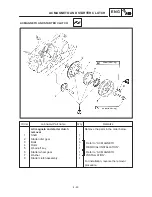
PRIMARY DRIVE GEAR INSTALLATION
1. Install:
Drive gear (oil pump)
1
Claw washer
Lock washer
Nut (primary drive gear)
Place a copper plate
2
between the teeth of
the primary drive gear
3
and primary driven
gear to lock them.
2. Bend:
Lock washer tab (along a flat side of the nut)
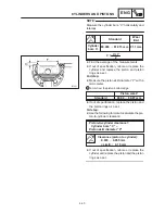
CLUTCH INSTALLATION
1. Install:
Lock washer
1
Nut (clutch boss)
2
Tighten the nut (clutch boss)
2
while holding
the clutch boss with a clutch holding tool
3
.
Clutch holding tool:
90890-04086
2. Bend:
Lock washer tab (along a flat side of the
nut)
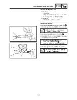
3. Install:
Friction plates
1
Clutch plates
2
Installation steps:
Install one friction plate and one clutch plate
alternately.
Summary of Contents for XVS6501997
Page 1: ......
Page 2: ......
Page 8: ......
Page 10: ...GEN INFO ...
Page 18: ...GEN INFO ...
Page 20: ...SPEC ...
Page 44: ...2 24 LUBRICATION DIAGRAMS SPEC 1 Crankshaft 2 Oil filter 3 Oil pump ...
Page 102: ...INSP ADJ ...
Page 188: ...CARB ...
Page 198: ...CARB ...
Page 266: ...CHAS ...
Page 268: ...ELEC SELF DIAGNOSIS 7 49 TROUBLESHOOTING 7 50 ...
Page 298: ...E 7 30 SIGNAL SYSTEM ELEC EB806000 SIGNAL SYSTEM CIRCUIT DIAGRAM ...
Page 320: ...TRBL SHTG ...
Page 326: ...TRBL SHTG ...

