E
7-36
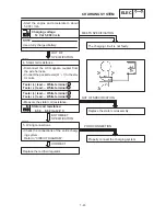
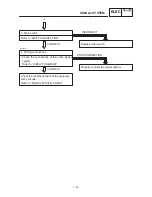
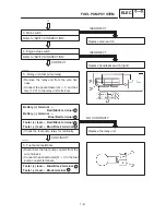
Turn the main switch to “ON”.
Check the voltage (12 V) of the “Brown”
lead at the flasher relay terminal.
The wiring circuit from the main switch to the
flasher relay connector is faulty, repair it.
OUT OF SPECIFICATION
MEETS
SPECIFICATION
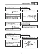
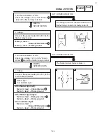
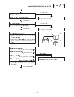
3. Voltage
Connect the pocket tester (DC 20 V) to the
flasher relay coupler.
Tester (+) lead
Brown / White terminal
Tester (–) lead
Frame ground
Turn the main switch to “ON”.
Check the voltage (12 V) on the “Brown /
White”
lead at the flasher relay terminal.
The flasher relay is faulty, replace it.
OUT OF SPECIFICATION
MEETS
SPECIFICATION
1
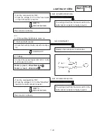
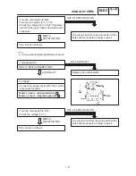
4. Voltage
Connect the pocket tester (DC 20 V) to the
bulb socket connector.
At the flasher light (left):
Tester (+) lead
Chocolate lead
Tester (–) lead
Frame ground
1
Flasher light
Turn indicator light
At the flasher light (right):
Tester (+) lead
Dark green lead
Tester (–) lead
Frame ground
At turn indicator light:
Tester (+) lead
Brown / White terminal
Tester (–) lead
Frame ground
A
B
A
B
1
1
2
3
SIGNAL SYSTEM
ELEC
Summary of Contents for XVS6501997
Page 1: ......
Page 2: ......
Page 8: ......
Page 10: ...GEN INFO ...
Page 18: ...GEN INFO ...
Page 20: ...SPEC ...
Page 44: ...2 24 LUBRICATION DIAGRAMS SPEC 1 Crankshaft 2 Oil filter 3 Oil pump ...
Page 102: ...INSP ADJ ...
Page 188: ...CARB ...
Page 198: ...CARB ...
Page 266: ...CHAS ...
Page 268: ...ELEC SELF DIAGNOSIS 7 49 TROUBLESHOOTING 7 50 ...
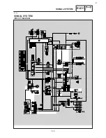
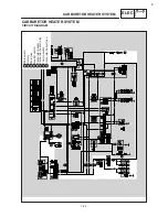
Page 298: ...E 7 30 SIGNAL SYSTEM ELEC EB806000 SIGNAL SYSTEM CIRCUIT DIAGRAM ...
Page 320: ...TRBL SHTG ...
Page 326: ...TRBL SHTG ...


