4-14
CYLINDER HEADS
ENG
35 Nm (3.5 m
S
kg)
20 Nm (2.0 m
S
kg)
NOTE:
*****************************************************
*****************************************************
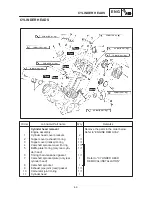
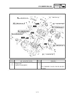
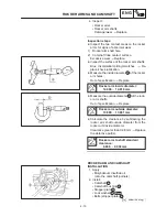
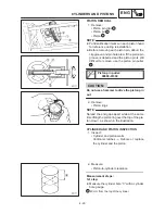
CYLINDER HEAD INSTALLATION
Rear cylinder head
1. Install:
S
Nuts (cylinder head) (M10:
1
4)
S
Bolts (cylinder head) (M8:
5
7)
D
Tighten the bolts and nuts in the proper se-
quence.
D
Follow the numerical order shown in the il-
lustration. Tighten the bolts and nuts in two
stages.
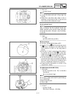
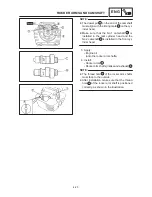
2. Install:
S
Camshaft sprocket
Installation steps:
D
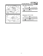
Turn the crankshaft clockwise.
D
Align the “T” mark
a
with the stationary
pointer
b
on the crankcase cover (left).
D
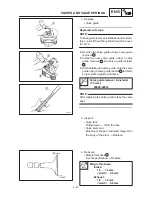
Install the camshaft sprocket with the timing
mark
c
facing out.
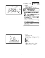
D
Turn the camshaft just enough to remove any
slack from the exhaust side of the timing
chain.
D
Insert your finger into the hole and timing
chain tensioner hole and push the timing
chain guide inward.
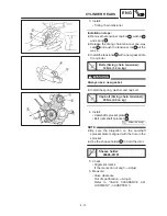
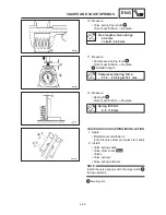
D
While pushing the timing chain guide, be sure
that the timing mark
c
and the stationary
pointer
d
are properly aligned at TDC.
Summary of Contents for XVS6501997
Page 1: ......
Page 2: ......
Page 8: ......
Page 10: ...GEN INFO ...
Page 18: ...GEN INFO ...
Page 20: ...SPEC ...
Page 44: ...2 24 LUBRICATION DIAGRAMS SPEC 1 Crankshaft 2 Oil filter 3 Oil pump ...
Page 102: ...INSP ADJ ...
Page 188: ...CARB ...
Page 198: ...CARB ...
Page 266: ...CHAS ...
Page 268: ...ELEC SELF DIAGNOSIS 7 49 TROUBLESHOOTING 7 50 ...
Page 298: ...E 7 30 SIGNAL SYSTEM ELEC EB806000 SIGNAL SYSTEM CIRCUIT DIAGRAM ...
Page 320: ...TRBL SHTG ...
Page 326: ...TRBL SHTG ...


