4-41
CLUTCH
ENG
*****************************************************
NOTE:
NOTE:
8 Nm (0.8 m
S
kg)
NOTE:
*****************************************************
*****************************************************
D
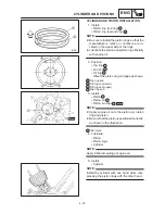
Apply engine oil onto the friction plates.
D
Align the two slots
a
on the friction plates
with the two punch marks
b
on the clutch
housing.
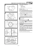
4. Install:
S
Push rod #2
S
Ball
S
Push rod #1
1
S
O-ring
2
S
Push plate
3
S
Washer
4
S
Nut
5
Apply lithium soap base grease onto the push
rod and the ball.
5. Install:
S
Pressure plate
1
S
Clutch springs
2
S
Bolts
3
Tighten the pressure plate bolts in stages, using
a crisscross pattern.
6. Check:
S
Push lever position
S
Push the push lever assembly in the direc-
tion of the arrow and make sure that the
match marks are aligned.
Match marks not aligned.
Adjust.
a Match mark on the push lever assembly
b Match mark on the crankcase
7. Adjust:
S
Push lever position
Adjustment steps:
D
Loosen the nut
1
.
D
Turn the push rod #1
2
clockwise or counter-
clockwise so that the match marks are
aligned.
D
Tighten the nut
1
.
Nut (clutch adjuster):
8 Nm (0.8 m
S
kg)
Summary of Contents for XVS6501997
Page 1: ......
Page 2: ......
Page 8: ......
Page 10: ...GEN INFO ...
Page 18: ...GEN INFO ...
Page 20: ...SPEC ...
Page 44: ...2 24 LUBRICATION DIAGRAMS SPEC 1 Crankshaft 2 Oil filter 3 Oil pump ...
Page 102: ...INSP ADJ ...
Page 188: ...CARB ...
Page 198: ...CARB ...
Page 266: ...CHAS ...
Page 268: ...ELEC SELF DIAGNOSIS 7 49 TROUBLESHOOTING 7 50 ...
Page 298: ...E 7 30 SIGNAL SYSTEM ELEC EB806000 SIGNAL SYSTEM CIRCUIT DIAGRAM ...
Page 320: ...TRBL SHTG ...
Page 326: ...TRBL SHTG ...


