4-76
MIDDLE GEAR
ENG
*****************************************************
CAUTION:
*****************************************************
90 Nm (9.0 m
kg)
NOTE:
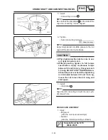
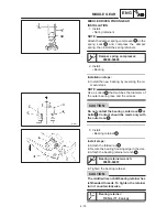
4. Install:
Middle driven shaft assembly
Install steps:
Clean the outside of the middle driven shaft
and the inside of the bearing.
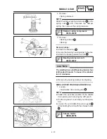
Fit the middle driven shaft assembly onto the
bearing housing.
Place the middle driven shaft assembly onto
a hydraulic press.
Never directly press the shaft end with a
hydraulic press, this will result in damage
to the shaft thread.
Install the hand-made tool
1
to protect
the bearing and bearing housing from
damage.
Install the wood piece
2
on the shaft end
to protect the thread from damage.
Press the wood piece and secure the middle
driven shaft assembly.
5. Tighten:
Nut (middle driven pinion gear)
1
Use the universal joint holder
2
to hold the
yoke
3
.
Universal joint holder:
90890-04062
6. Install:
Yoke (cross joint)
1
(into the hole on yoke)
Summary of Contents for XVS6501997
Page 1: ......
Page 2: ......
Page 8: ......
Page 10: ...GEN INFO ...
Page 18: ...GEN INFO ...
Page 20: ...SPEC ...
Page 44: ...2 24 LUBRICATION DIAGRAMS SPEC 1 Crankshaft 2 Oil filter 3 Oil pump ...
Page 102: ...INSP ADJ ...
Page 188: ...CARB ...
Page 198: ...CARB ...
Page 266: ...CHAS ...
Page 268: ...ELEC SELF DIAGNOSIS 7 49 TROUBLESHOOTING 7 50 ...
Page 298: ...E 7 30 SIGNAL SYSTEM ELEC EB806000 SIGNAL SYSTEM CIRCUIT DIAGRAM ...
Page 320: ...TRBL SHTG ...
Page 326: ...TRBL SHTG ...


