4-29
CYLINDERS AND PISTONS
ENG
NOTE:
CAUTION:
NOTE:
*****************************************************
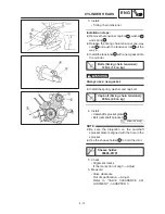
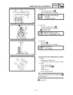
PISTON REMOVAL
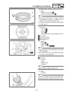
1. Remove:
S
Piston pin clips
1
S
Piston pin
2
S
Piston
3
D
Put identification marks on each piston head
for reference during reinstallation.
D
Before removing each piston pin, deburr the
clip groove and pin hole area. If the piston pin
groove is deburred and the piston pin is still
difficult to remove, use the piston pin puller
4
.
Piston pin puller:
90890-01304
Do not use a hammer to drive the piston pin
out.
2. Remove:
S
Piston rings
Spread the end gaps apart while at the same
time lifting the piston ring over the top of the pis-
ton crown, as shown in the illustration.
CYLINDER AND PISTON INSPECTION
1. Inspect:
S
Cylinder and piston walls
Vertical scratches
Rebore or replace
the cylinder and the piston.
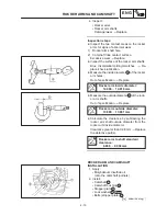
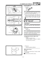
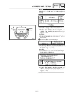
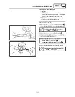
2. Measure:
S
Piston-to-cylinder clearance
Measurement steps:
1st step:
D
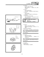
Measure the cylinder bore “C” with a cylinder
bore gauge.
a 40 mm from the top of the cylinder
Summary of Contents for XVS6501997
Page 1: ......
Page 2: ......
Page 8: ......
Page 10: ...GEN INFO ...
Page 18: ...GEN INFO ...
Page 20: ...SPEC ...
Page 44: ...2 24 LUBRICATION DIAGRAMS SPEC 1 Crankshaft 2 Oil filter 3 Oil pump ...
Page 102: ...INSP ADJ ...
Page 188: ...CARB ...
Page 198: ...CARB ...
Page 266: ...CHAS ...
Page 268: ...ELEC SELF DIAGNOSIS 7 49 TROUBLESHOOTING 7 50 ...
Page 298: ...E 7 30 SIGNAL SYSTEM ELEC EB806000 SIGNAL SYSTEM CIRCUIT DIAGRAM ...
Page 320: ...TRBL SHTG ...
Page 326: ...TRBL SHTG ...

