4-11
CYLINDER HEADS
ENG
*****************************************************
*****************************************************
NOTE:
NOTE:
CYLINDER HEAD REMOVAL
Rear cylinder head
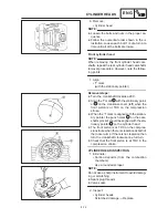
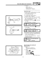
1. Align:
S
“T” mark
(with the stationary pointer)
Removal steps:
D
Temporarily install the AC magneto cover
without the pickup coil and stator coil.
D
Turn the crankshaft clockwise.
D
Align the “T” mark
a
with the stationary
pointer
b
on the crankcase cover (left) when
the rear piston is at TDC on the compression
stroke.
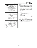
D
When the “T” mark is aligned with the station-
ary pointer the punch mark
c
on the cam-
shaft sprocket should be aligned with the sta-
tionary pointer
d
on the cylinder head.
D
The rear piston is at TDC on the compression
stroke when there is clearance at both of the
rocker arms. If there is no clearance then turn
the crankshaft clockwise one full turn.
D
Check that the rear piston is at TDC in the
compression stroke.
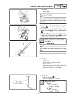
2. Loosen:
S
Bolt (camshaft sprocket)
1
Use the sheave holder
2
to hold the rotor.
Sheave holder:
90890-01701
3. Loosen:
S
Cap bolt (timing chain tensioner)
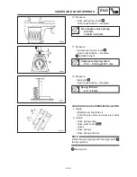
4. Remove:
S
Timing chain tensioner
S
Gasket
5. Remove:
S
Bolt (camshaft sprocket)
1
S
Camshaft sprocket plate
2
(only rear)
S
Camshaft sprocket
3
To prevent the timing chain from falling into the
crankcase fasten a wire to it.
Summary of Contents for XVS6501997
Page 1: ......
Page 2: ......
Page 8: ......
Page 10: ...GEN INFO ...
Page 18: ...GEN INFO ...
Page 20: ...SPEC ...
Page 44: ...2 24 LUBRICATION DIAGRAMS SPEC 1 Crankshaft 2 Oil filter 3 Oil pump ...
Page 102: ...INSP ADJ ...
Page 188: ...CARB ...
Page 198: ...CARB ...
Page 266: ...CHAS ...
Page 268: ...ELEC SELF DIAGNOSIS 7 49 TROUBLESHOOTING 7 50 ...
Page 298: ...E 7 30 SIGNAL SYSTEM ELEC EB806000 SIGNAL SYSTEM CIRCUIT DIAGRAM ...
Page 320: ...TRBL SHTG ...
Page 326: ...TRBL SHTG ...


