5-8
CARBURETOR
CARB
NOTE:
*****************************************************
*****************************************************
1
2
3
1
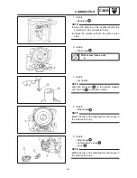
THROTTLE POSITION SENSOR (TPS) IN-
SPECTION AND ADJUSTMENT
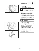
Before adjusting the TPS, the idling speed
should be properly adjusted.
1. Inspect:
S
TPS resistance
Inspect steps:
D
Disconnect the TPS coupler.
D
Remove the TPS from the carburetor.
D
Connect the pocket tester (
Ω
1 k) to the
TPS connector.
Tester (+) lead
Black terminal
Tester (–) lead
Blue terminal
D
Check the TPS resistance.
TPS resistance “R
1
”:
4.0
X
6.0 k
Ω
at 20
_
C
(Black — Blue)
Out of specification
Replace the TPS.
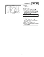
D
Connect the pocket tester (
Ω
1 k) to the
TPS connector.
T
ester (+) lead
Yellow terminal
Tester (–) lead
Black terminal
D
While slowly turning the throttle check the
TPS resistance.
TPS resistance “R
2
”:
0
X
5
±
1.0 k
Ω
at 20
_
C
(Yellow — Black)
Out of specification
Replace the TPS.
Summary of Contents for XVS6501997
Page 1: ......
Page 2: ......
Page 8: ......
Page 10: ...GEN INFO ...
Page 18: ...GEN INFO ...
Page 20: ...SPEC ...
Page 44: ...2 24 LUBRICATION DIAGRAMS SPEC 1 Crankshaft 2 Oil filter 3 Oil pump ...
Page 102: ...INSP ADJ ...
Page 188: ...CARB ...
Page 198: ...CARB ...
Page 266: ...CHAS ...
Page 268: ...ELEC SELF DIAGNOSIS 7 49 TROUBLESHOOTING 7 50 ...
Page 298: ...E 7 30 SIGNAL SYSTEM ELEC EB806000 SIGNAL SYSTEM CIRCUIT DIAGRAM ...
Page 320: ...TRBL SHTG ...
Page 326: ...TRBL SHTG ...


