2 - 36
SPEC
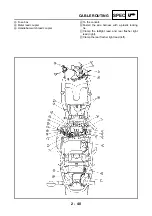
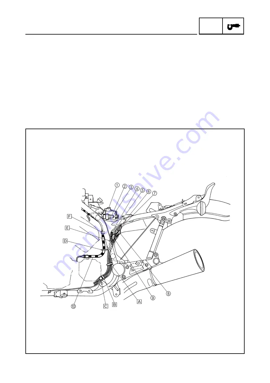
CABLE ROUTING
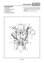
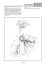
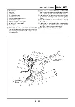
1
Starter relay
2
Main fuse
3
Ignition coil
4
Oil level switch lead
5
Neutral switch lead
6
Rectifier/regulator lead coupler
7
Ground lead coupler
8
Sidestand switch lead coupler
9
AC generator lead coupler
0
Clutch hose
È
Fasten the oil level switch lead, neutral switch
lead, ground lead, sidestand switch lead, overflow
hose and AC generator lead with a plastic band to
the frame guide.
É
Fasten the oil level switch lead, neutral switch
lead, ground lead, sidestand switch lead, overflow
hose and AC generator lead with plastic band.
Ê
Pass the oil level switch lead, neutral switch lead,
ground lead, and AC generator lead through the
clamp.
Ë
Pass the clutch hose and overflow hose through
the guide.
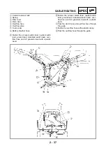
Ì
Fasten the oil level switch lead, neutral switch
lead, ground lead, sidestand switch lead and AC
generator lead with a plastic locking tie.
Í
Pass the clutch hose through the guide.
Summary of Contents for VMX12 2001
Page 1: ...VMX12 2001 3LRD AE1 SERVICEMANUAL ...
Page 2: ......
Page 8: ......
Page 9: ...GEN INFO 1 ...
Page 11: ...GEN INFO ...
Page 21: ......
Page 22: ...SPEC 2 ...
Page 24: ...SPEC ...
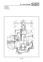
Page 52: ...2 28 SPEC OIL FLOW DIAGRAMS 1 Camshaft 2 Main gallery 3 Crankshaft 4 Oil level switch ...
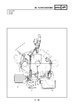
Page 54: ...2 30 SPEC OIL FLOW DIAGRAMS 1 Crankshaft 2 Oil pipe 3 Oil filter ...
Page 65: ...CHK ADJ 3 ...
Page 125: ......
Page 126: ...ENG 4 ...
Page 130: ...ENG ...
Page 236: ......
Page 237: ...COOL 5 ...
Page 239: ...COOL ...
Page 258: ...CARB 6 ...
Page 260: ...CARB ...
Page 272: ......
Page 273: ...CHAS 7 ...
Page 389: ......
Page 390: ...ELEC 8 ...
Page 396: ...8 4 ELEC SWITCHES ...
Page 417: ...8 25 ELEC STARTER MOTOR 3 Install O rings 1 bolts 2 New T R 5 Nm 0 5 m kg ...
Page 445: ...TRBL SHTG 9 ...

