4 - 82
ENG
CONNECTING RODS AND PISTONS
5. Select:
• big end bearings (P
1
~ P
2
)
NOTE:
@
• The numbers
È
stamped into the crankshaft
web and the numbers
1
on the connecting
rods are used to determine the replacement
big end bearing sizes.
• “P
1
” ~ “P
2
” refer to the bearings shown in the
crankshaft illustration.
@
For example, if the connecting rod “P
1
” and the
crankshaft web “P
1
” numbers are “4” and “1”
respectively, then the bearing size for “P
1
” is:
▲▲▲▲▲▲▲▲▲▲▲▲▲▲▲▲▲▲▲▲▲▲▲▲▲▲▲▲▲▲▲
Bearing size of P
1
:
“P
1
” (connecting rod) – “P
1
” (crank-
shaft web)
4 – 1 = 3 (brown)
BEARING COLOR CODE
1
blue
2
black
3
brown
4
green
5
yellow
6
pink
EAS00270
INSTALLING THE PISTONS AND
CYLINDERS
The following procedure applies to all of the
pistons and cylinders.
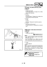
1. Install:
• top ring
• 2nd ring
• oil ring
NOTE:
@
• Be sure to install the piston rings so that the
manufacturer’s marks or numbers are
located on the upper side of the rings.
• Lubricate the piston and piston rings liberally
with engine oil.
@
Summary of Contents for VMX12 2001
Page 1: ...VMX12 2001 3LRD AE1 SERVICEMANUAL ...
Page 2: ......
Page 8: ......
Page 9: ...GEN INFO 1 ...
Page 11: ...GEN INFO ...
Page 21: ......
Page 22: ...SPEC 2 ...
Page 24: ...SPEC ...
Page 52: ...2 28 SPEC OIL FLOW DIAGRAMS 1 Camshaft 2 Main gallery 3 Crankshaft 4 Oil level switch ...
Page 54: ...2 30 SPEC OIL FLOW DIAGRAMS 1 Crankshaft 2 Oil pipe 3 Oil filter ...
Page 65: ...CHK ADJ 3 ...
Page 125: ......
Page 126: ...ENG 4 ...
Page 130: ...ENG ...
Page 236: ......
Page 237: ...COOL 5 ...
Page 239: ...COOL ...
Page 258: ...CARB 6 ...
Page 260: ...CARB ...
Page 272: ......
Page 273: ...CHAS 7 ...
Page 389: ......
Page 390: ...ELEC 8 ...
Page 396: ...8 4 ELEC SWITCHES ...
Page 417: ...8 25 ELEC STARTER MOTOR 3 Install O rings 1 bolts 2 New T R 5 Nm 0 5 m kg ...
Page 445: ...TRBL SHTG 9 ...


