8 - 14
–
+
ELEC
IGNITION SYSTEM
YES
NO
YES
NO
EAS00754
YES
NO
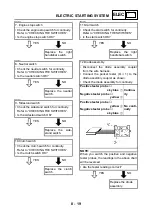
12.Diode assembly
• Disconnect the diode assembly coupler
from the wire harness.
• Connect the pocket tester (
Ω
×
1) to the
diode assembly coupler as shown.
• Check the diode assembly for continuity.
Positive tester probe
→
sky blue
1
Negative tester probe
→
yellow
2
Continu-
ity
Positive tester probe
→
yellow
2
Negative tester probe
→
sky blue
1
No conti-
nuity
NOTE:
@
When you switch the positive and negative
tester probes, the readings in the above chart
will be reversed.
@
• Are the tester readings correct?
Replace the diode
assembly.
13.Vacuum pressure sensor
• Disconnect the vacuum pressure sensor
coupler from the wire harness.
• Connect the pocket tester (DC 20 V) and
battery (12 V) to the vacuum pressure sen-
sor terminals as shown.
Battery positive terminal
→
red/black
1
Battery negative terminal
→
black/yellow
2
Tester positive probe
→
black/red
3
Tester negative probe
→
black/yellow
2
• Measure the vacuum pressure sensor out-
put voltage.
Vacuum pressure sensor out put
voltage
2.0 V at 0 Pa (0 bar)
• Is the vacuum pressure sensor OK?
Replace the vacuum
pressure sensor.
14.Wiring connections
• Check the entire ignition system’s wiring.
Refer to “CIRCUIT DIAGRAM”.
• Is the ignition system’s wiring properly con-
nected and without defects?
Replace the ignitor
unit.
Properly connect or
repair the ignition
system’s wiring.
Summary of Contents for VMX12 2001
Page 1: ...VMX12 2001 3LRD AE1 SERVICEMANUAL ...
Page 2: ......
Page 8: ......
Page 9: ...GEN INFO 1 ...
Page 11: ...GEN INFO ...
Page 21: ......
Page 22: ...SPEC 2 ...
Page 24: ...SPEC ...
Page 52: ...2 28 SPEC OIL FLOW DIAGRAMS 1 Camshaft 2 Main gallery 3 Crankshaft 4 Oil level switch ...
Page 54: ...2 30 SPEC OIL FLOW DIAGRAMS 1 Crankshaft 2 Oil pipe 3 Oil filter ...
Page 65: ...CHK ADJ 3 ...
Page 125: ......
Page 126: ...ENG 4 ...
Page 130: ...ENG ...
Page 236: ......
Page 237: ...COOL 5 ...
Page 239: ...COOL ...
Page 258: ...CARB 6 ...
Page 260: ...CARB ...
Page 272: ......
Page 273: ...CHAS 7 ...
Page 389: ......
Page 390: ...ELEC 8 ...
Page 396: ...8 4 ELEC SWITCHES ...
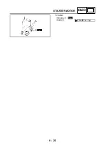
Page 417: ...8 25 ELEC STARTER MOTOR 3 Install O rings 1 bolts 2 New T R 5 Nm 0 5 m kg ...
Page 445: ...TRBL SHTG 9 ...


