6 - 10
CARB
CARBURETORS
EAS00495
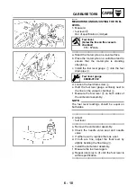
MEASURING AND ADJUSTING THE FUEL
LEVEL
1. Measure:
• fuel level
a
Out of specification
→
Adjust.
▼▼▼▼▼▼▼▼▼▼▼▼▼▼▼▼▼▼▼▼▼▼▼▼▼▼▼▼▼▼▼
a. Stand the motorcycle on a level surface.
b. Place the motorcycle on a suitable stand to
ensure that the motorcycle is standing
straight up.
c. Install the fuel level gauge
1
onto the fuel
drain pipe
2
.
d. Loosen the fuel drain screw
3
.
e. Hold the fuel level gauge vertically next to
the line on the vacuum chamber
4
.
f. Measure the fuel level
a
on both sides of
the carburetor assembly.
NOTE:
@
The fuel level readings should be equal on
both sides.
@
▲▲▲▲▲▲▲▲▲▲▲▲▲▲▲▲▲▲▲▲▲▲▲▲▲▲▲▲▲▲▲
Fuel level
(below the line on the vacuum
chamber)
15 ~ 17 mm
Fuel level gauge
90890-01312
2. Adjust:
• fuel level
▼▼▼▼▼▼▼▼▼▼▼▼▼▼▼▼▼▼▼▼▼▼▼▼▼▼▼▼▼▼▼
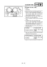
a. Remove the carburetor assembly.
b. Check the needle valve seat and needle
valve.
c. If either is worn, replace them as a set.
d. If both are fine, adjust the float level by
slightly bending the float tang
1
.
e. Install the carburetor assembly.
f. Measure the fuel level again.
g. Repeat steps (a) to (f) until the fuel level is
within specification.
▲▲▲▲▲▲▲▲▲▲▲▲▲▲▲▲▲▲▲▲▲▲▲▲▲▲▲▲▲▲▲
Summary of Contents for VMX12 2001
Page 1: ...VMX12 2001 3LRD AE1 SERVICEMANUAL ...
Page 2: ......
Page 8: ......
Page 9: ...GEN INFO 1 ...
Page 11: ...GEN INFO ...
Page 21: ......
Page 22: ...SPEC 2 ...
Page 24: ...SPEC ...
Page 52: ...2 28 SPEC OIL FLOW DIAGRAMS 1 Camshaft 2 Main gallery 3 Crankshaft 4 Oil level switch ...
Page 54: ...2 30 SPEC OIL FLOW DIAGRAMS 1 Crankshaft 2 Oil pipe 3 Oil filter ...
Page 65: ...CHK ADJ 3 ...
Page 125: ......
Page 126: ...ENG 4 ...
Page 130: ...ENG ...
Page 236: ......
Page 237: ...COOL 5 ...
Page 239: ...COOL ...
Page 258: ...CARB 6 ...
Page 260: ...CARB ...
Page 272: ......
Page 273: ...CHAS 7 ...
Page 389: ......
Page 390: ...ELEC 8 ...
Page 396: ...8 4 ELEC SWITCHES ...
Page 417: ...8 25 ELEC STARTER MOTOR 3 Install O rings 1 bolts 2 New T R 5 Nm 0 5 m kg ...
Page 445: ...TRBL SHTG 9 ...

