background image

Track recording

50

Using the input library

The input library is a library of settings used to apply 
internal effects, EQ, or dynamics settings to the input sig-
nal when you want to record the processed signal. Here’s 
how to apply input library settings to the signal of an 
input channel.

1

Press and hold the [INPUT SEL] key of the 
input channel for which you want to use the 
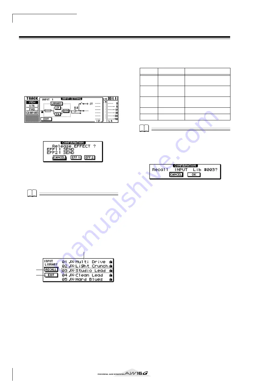
input library. The INPUT SETTING popup 
window will appear.

2

Move the cursor to the LIBRARY button, and 
press the [ENTER] key.

The following popup window will appear.
In this popup window, you can select whether the 
internal effect 1 or 2 will be patched to the input 
channel.

Note

Note

When you use the input library, internal effect 1 or 2 will 
be disconnected from the send/return of the mixer, and 
patched to a specific input channel. For this reason, you 
can use the internal effects on a maximum of two chan-
nels.

3

Move the cursor to the EFF1 button or EFF2 
button, and press the [ENTER] key.

The INPUT LIBRARY popup window will appear, 
allowing you to select an input library.

1

List

This is the library list. The line surrounded by a dot-
ted line in the middle of the list is the data that is 
selected for loading. When you turn the [DATA/
JOG] dial, the data in the list will scroll upward or 
downward.

B

RECALL button

Move the cursor to this button and press the 
[ENTER] key to load the currently selected data.

C

EXIT button

Move the cursor to this button and press the 
[ENTER] key to close the popup window.

4

Turn the [DATA/JOG] dial to select the 
desired input library data.

The input library data is organized into the follow-
ing categories.

Note

Note

All input library data is read-only.

5

Select the desired data, and press the 
[ENTER] key.

A popup window will ask you to confirm the recall 
operation.

6

Move the cursor to the OK button and press 
the [ENTER] key.

The data of the selected library will be loaded, and 
the internal effect, EQ (or speaker simulator), and 
dynamics effect will be applied to the input signal.

2
3

1

Number Abbreviation

Category

00

Data for initializing the 
input channel

01–25

EG

Data suitable for electric 
guitar.

26–30

AG

Data suitable for acoustic 
guitar.

31–35

BA

Data suitable for bass.

36–40

VO

Data suitable for vocals

Summary of Contents for AW 16G

Page 1: ...E Owner s Manual Owner s Manual Owner s Manual Keep This Manual For Future Reference ...

Page 2: ...unit OFF and ON please try to eliminate the problem by using one of the following measures Relocate either this product or the device that is being affected by the interference Utilize power outlets that are on different branch circuit breaker or fuse circuits or install AC line filter s In the case of radio or TV interference relocate reorient the antenna If the antenna lead in is 300 ohm ribbon ...

Page 3: ...is a fire and elec trical shock hazard Should this unit and AC adaptor be dropped or the cabinet be damaged turn the power switch off remove the power plug from the AC outlet and con tact your dealer If you continue using the unit with out heeding this instruction fire or electrical shock may result If you notice any abnormality such as smoke odor or noise or if a foreign object or liquid gets ins...

Page 4: ...e recorded data being lost the drive to malfunction or the printed label to become blurred Do not place the disc in locations of direct sunlight high temperature or high humidity Do not touch either surface of the disc Hold the disc at the edges Gently wipe dust or dirt off of the recording surface of the disc Use an air duster or cleaner to remove dust Vigorously rubbing the surface of the disc w...

Page 5: ...countries permit reproduction of copyrighted mate rials under certain requirements The observance of applicable laws for use of this product however is your responsibility Yamaha disclaims any liability for violation of such laws in association with the use of this prod uct Although this product is designed for original music production it can be utilized to make reproduction of copyrighted music ...

Page 6: ...52 Using the dynamics library 53 6 Overdubbing 55 About overdubbing 55 Assigning the input signal to a track 56 Instantly recalling an EQ library 56 Instantly recalling a dynamics library 57 Setting the mix balance and pan 57 Overdubbing 58 Punch in out 59 Manual punch in out 59 Auto punch in out 59 Using the Undo List 61 Switching virtual tracks 62 Saving the current song 63 Loading an existing s...

Page 7: ...name 138 Editing various settings for the song 139 Copying or deleting a song 140 Optimizing a song 141 Creating a tempo map 142 Importing data from an existing song 144 Backing up songs and sample libraries 145 Restoring songs or sample libraries 147 Exchanging song data with the AW4416 AW2816 148 14 MIDI and utility functions 149 What you can do using MIDI 149 Basic MIDI settings 150 Transmittin...

Page 8: ...Contents 8 ...

Page 9: ...emark of Steinberg Media Tech nologies AG Logic Audio is a trademark of Emagic Soft and Hard ware GmbH Cakewalk is a registered trademark of Twelve Tone Systems Inc ProTools is a trademark or registered trademark of Avid Technology Inc and affiliated companies Other company names and product names in this document are the trademarks or registered trade marks of their respective owners Yamaha websi...

Page 10: ... particular any metallic fragments screws or pins that enter the drive mechanism will cause opera tion to fail G Do not press on the upper cover Installing the CD RW drive 1 Turn off the power of the AW16G As described in Turning the power off shut down p 12 turn off the power of the AW16G For safety s sake also unplug the AC adaptor and the AW16G from the electrical outlet 2 Turn the AW16G over o...

Page 11: ...he AW16G you must remove this protective pad To insert a disc into the CD RW drive press the eject switch The disc tray will open Place the disc on the tray and gently push the disc tray in Note Note The disc tray is ejected electrically If the disc tray is not ejected when you press the eject switch turn on the power of the AW16G and press the eject switch once again Removing a CD in an emergency...

Page 12: ... the AW16G turn the power of each device off in the following order 1 The monitor system connected to the AW16G s output jacks B The AW16G itself C External devices such as audio sources and effect processors connected to the input out put jacks of the AW16G When turning off the power of the AW16G you must perform the following shut down procedure 1 In the work navigate section located in the uppe...

Page 13: ...uaranteed by 24 bit AD DA and 32 bit internal processing A Hi Z input jack for directly connecting an electric guitar or bass is also provided Totally redesigned operation The AW16G is designed to be operated directly by the musician guitarist vocalist drummer etc With a minimum number of steps you can assign input signals to tracks switch the monitor signal and record with effects EQ and dynamics...

Page 14: ...range of one octave upward or downward You can use the Undo function to reverse the results of as many as the last fifteen editing operations A variety of Locate methods and auto punch in out Seven locate points start end relative zero A B in out and 99 markers can be assigned at any desired point in the song for quick access via Locate opera tions Auto punch in out and A B repeat playback functio...

Page 15: ...ocate points Locate points include the in out points and the A B points and you can use the keys of the Locate section to move instantly to these points Independently of the locate points you can assign markers at desired locations within a song so that you will be able to find these locations quickly The AW16G lets you set up to ninety nine markers 1 99 By using the keys of the Locate section you...

Page 16: ... of track input channels and send them to recorder track inputs Quick Loop Sampler section Sample banks and samples In the Quick Loop Sampler section you can assign stereo waveforms to the four pads and strike the pads to play them back These stereo waveforms are called samples The memories to which the samples are assigned are called sample banks and each pad provides four sam ple banks A D Pad t...

Page 17: ...ious items on the AW16G s top panel rear panel and front panel Top panel Locate section P 20 Transport section P 21 Data entry control section P 20 Selected Channel section P 19 Input output section P 18 Work Navigate section P 18 Quick Navigate section P 18 Display P 18 Mixer section P 19 Quick Loop Sampler section P 18 ...

Page 18: ...k Quick Navigate section 1 RECORD key This key accesses the RECORD screen where you can quickly assign the signal to be recorded to the input of each track and make settings for recording B MONITOR key This key accesses the MONITOR screen where you can quickly select the signal to be monitored or switch the stereo track playback on off Display This is a backlit liquid crystal display that indicate...

Page 19: ...ected channel You can press this knob to access the DYN screen where you can adjust all of the dynamics settings C EFF 1 knob D EFF 2 knob Turning these knobs will adjust the amount of signal that is sent from the currently selected channel to the internal effects 1 and 2 i e effect send levels 1 and 2 You can press these knobs to access the EFF1 or EFF2 screens where you can adjust the parameters...

Page 20: ...pecific function Locate section 1 SOUND CLIP key This key accesses the CLIP screen where you can record or play sound clips B AUTO PUNCH key This key switches the audio punch in out function on off letting you automate recording C REPEAT key This key switches the A B repeat function on off let ting you repeatedly play a specified region D MARK SEARCH keys These keys search for markers placed withi...

Page 21: ...is key and press the PLAY key during playback you will switch from playback to recording punch in Rear panel 1 MIC LINE INPUT XLR jacks 1 2 These are XLR 3 31 type balanced input jacks The nominal input level is 46 to 4 dB Mics direct boxes or line level devices with balanced output jacks can be connected here The pin configuration is shown below B MIC LINE INPUT TRS phone jacks 3 8 These are TRS ...

Page 22: ...ated within the AW16G or MIDI THRU jack which re transmits messages that are received at the MIDI IN jack K DIGITAL STEREO IN OUT jacks These are optical jacks that allow digital audio sig nals to be exchanged with external devices They support the IEC958 consumer format L Grounding terminal This is a terminal for electrically grounding the AW16G To prevent electrical shock you must con nect this ...

Page 23: ...ect are displayed in the main screen Cursor The blinking frame within the display is called the cursor When an object in the screen is enclosed by the cursor that object is selected for operations Buttons Buttons in the display are used to switch a parameter on off to select one of multiple choices or to exe cute a specific function A button that is currently on will be dis played in black with wh...

Page 24: ...memory or library setting a popup window will appear allowing you to assign a name for the song or setting This popup window contains the following items and functions 1 Text input box This box lets you input characters numerals and symbols When you save the data for the first time the box will contain a default name You can input a scene library name or song name of up to twelve characters B Text...

Page 25: ...ccess the follow ing screens EQ screen EDIT page 4 Move the cursor in the screen to the desired parameter and use the DATA JOG dial or the ENTER key to operate the parameter Note Note If you change individual parameters in the DYN screen the parameter that you operate last will be assigned to the DYN knob If you want to return to the state in which turning the DYN knob will adjust multiple paramet...

Page 26: ...Introducing the AW16G 26 ...

Page 27: ...processors connected to the input out put jacks of the AW16G B The AW16G itself C The monitor system connected to the output jacks of the AW16G After the opening screen the following screen will appear When you turn on the power of the AW16G the last used song will be loaded automatically When you turn on the power of the AW16G with the factory settings a blank song will be loaded so you can start...

Page 28: ...s the song that is currently loaded into the AW16G This is called the current song B SORT field These three buttons let you select how the songs in the list will be sorted Choose the NAME button sort alphabetically OLD button sort by save date or SIZE button sort by size 3 Turn the DATA JOG dial to select the song Ride with me 4 Move the cursor to the LOAD button in the screen and press the ENTER ...

Page 29: ...ther TRACK 1 8 or TRACK 9 10 15 16 If neither of these are displayed press either the TRACK SEL key 1 8 or 9 10 15 16 2 Lower the AW16G s STEREO fader to the infinity position Also make sure that the AW16G s MONITOR PHONES knob and the volume of your monitor system are turned down 3 Press the PLAY key The demo song will begin playing and the level of each track channel will be displayed in the MET...

Page 30: ... from the STEREO AUX OUT jacks or the MONITOR OUT jacks Signal flow during song playback Track channels 1 8 and 9 10 15 16 are directly con trolled by the faders and TRACK SELECT keys of the panel Here s how you can adjust the mix level of each track channel and switch it on off while the song plays back Recorder section Mixer section Stereo bus Track channels Stereo output channel Track 1 Track 2...

Page 31: ... pressing the STEREO SEL key will have no effect 6 To cancel the muted state press the same TRACK SEL key you pressed in step 5 to make the indicator light green 7 If you want to monitor the playback of just a specific track access the MONITOR screen SOLO page by either repeatedly pressing the MONITOR key or by holding down the MONITOR key and using the CURSOR keys The SOLO page of the MONITOR scr...

Page 32: ...Listening to the demo song 32 ...

Page 33: ...your mic direct box or a guitar bass preamp that has a balanced out put jack MIC LINE INPUT TRS phone jacks 3 8 These are TRS type balanced input jacks Use a 1 4 TRS phone female XLR cable to connect your mic direct box or a guitar bass preamp that has a bal anced output jack Alternatively you can use a 1 4 phone 1 4 phone cable to connect an instrument with unbal anced output such as a synthesize...

Page 34: ...ile you watch the level meter in the popup window produce sound on your instrument and turn the GAIN knob to adjust the input level As you turn the GAIN knob toward the right the level meter in the popup window will move more widely However you will not yet hear anything from your monitor system For the best audio quality adjust the level as high as possible without allowing the meter to clip when...

Page 35: ...back the sig nal will be sent immediately before the stereo output channel fader EQ and dynamics cannot be applied to the playback of a sound clip Signal flow when using a sound clip REC SONG SCENE MUSIC PRODUCTION SYNTHESIZER Integrated Sampling Sequencer Real time External Control Surface Modular Synthesis Plug in System Mixer section Stereo bus Input channels Stereo output channel MIC LINE INPU...

Page 36: ...ited from this screen For details on tempo map set tings p 142 4 In the Transport section hold down the REC key and press the PLAY key The metronome will begin sounding and the counter display will advance The counter in the CLIP screen always starts from 0 and indicates the current time in minutes seconds milliseconds This counter is separate from the counter of a conven tional song 5 Play your i...

Page 37: ...OPY com mand p 128 5 To execute the CLIP screen press the SOUND CLIP key A popup window will ask you for confirmation Move the cursor to the OK button to exit the CLIP screen or to the CANCEL button to cancel and press the ENTER key When you exit the CLIP screen you will return to the TRACK screen VIEW page However you can press the SOUND CLIP key at any time to play back the previously recorded c...

Page 38: ...Recording to a sound clip 38 ...

Page 39: ...r allowing you to specify the items whose settings will be carried over from the current song You may choose one or more of the following items if desired SCENE button Scene memories LIBRARY button EQ dynamics effects and channel libraries TEMPO button Tempo map For example if you have saved effect settings in a library for the current song and would like to use these settings for the new song as ...

Page 40: ...e correspondence This method requires the same number of tracks as the number of input channels you use However this method has the advantage that you will be free to adjust the vol ume pan stereo position and tone of each instru ment after it has been recorded Synthesizer rhythm machine Mixer section Input channels Stereo output channel MIC LINE INPUT jacks Recorder section Track 1 Track 2 Track ...

Page 41: ...final vol ume pan and tone of each instrument at the time of recording You will not be able to adjust these inde pendently after recording Note Note The way in which you assign the input signals to tracks will depend on the method you choose L R bus Synthesizer rhythm machine Mixer section Input channels Stereo output channel MIC LINE INPUT jacks Recorder section Track 1 Track 2 Track 3 Track 4 Tr...

Page 42: ...rsor to this button and press the ENTER key input channels 1 8 will be connected to tracks 1 8 D 9 16 button If you move the cursor to this button and press the ENTER key input channels 1 8 will be connected to tracks 9 16 E SAFE button If you move the cursor to this button and press the ENTER key all connections will be cancelled 4 Press the INPUT SEL key for the input chan nel to which your inst...

Page 43: ...ed even numbered channels will be simultaneously assigned to two adjacent odd numbered even num bered tracks 7 Press and hold the INPUT SEL key for the recording source input channel to access the INPUT SETTING popup window Tip Tip You can also access the INPUT SETTING popup window by moving the cursor to an input channel number in the RECORD screen DIRECT page and pressing the ENTER key 8 Use the...

Page 44: ... and turn the PAN BAL knob of the Selected Channel section Note Note The pan setting of an input channel will have no effect if that input channel is assigned to a track by direct record ing Mixer section Track channels Stereo out put channel Recorder section from the input channels Stereo bus Track 1 Track 2 Track 3 Track 4 Track 5 Track 6 Track 7 Track 8 ...

Page 45: ...the right of the screen You can use this to adjust the master level of the L R bus 4 Press the INPUT SEL key for the input chan nel to which you connected your instrument or mic The current setting INPUT SEL key will light orange and that input channel will be selected for operations In the screen the symbol for the corresponding input channel will be highlighted and a line will appear indicat ing...

Page 46: ...t the monitor level is appropriate Now you will be able to monitor the signal that is being sent to the track s via the L R bus 11To set the pan of each input channel use the INPUT SEL key to select a channel and turn the PAN BAL knob of the Selected Channel section When you use bus recording it will not be possible to adjust the pan or volume balance for individual instruments after they have bee...

Page 47: ...ss the SONG key or hold down the SONG key and use the CURSOR keys to access the TEMPO page The TEMPO page lets you create a tempo map that specifies the tempo and time signature of the song The tempo and time signature that you specify here will be the basis for the measure beat display counter the internal metronome and the MIDI clock messages generated by the AW16G 1 Tempo map events These are t...

Page 48: ... the track view within the screen the vertical line that indicates the current location will advance toward the right 3 Play your instrument in time with the metro nome The metronome sound will not be recorded on the track If necessary move the cursor to the metro nome knob and turn the DATA JOG dial to adjust the metronome volume level 4 To stop recording press the STOP key I In point and O Out p...

Page 49: ...PUT TRACK y x x odd number y even number Copy the settings of input track channel y to x and pair them RESET BOTH Initialize both input track chan nels and pair them CANCEL Cancel pairing When input channels are paired all mix parameters other than the GAIN knob and phase pan settings will be linked When track channels are paired all mix parameters other than the phase pan settings will be paired ...

Page 50: ...r allowing you to select an input library 1 List This is the library list The line surrounded by a dot ted line in the middle of the list is the data that is selected for loading When you turn the DATA JOG dial the data in the list will scroll upward or downward B RECALL button Move the cursor to this button and press the ENTER key to load the currently selected data C EXIT button Move the cursor ...

Page 51: ... to adjust the dynamics effect The result will depend on the library that you selected Turning the EFF 1 knob Adjusts the balance of direct sound and processed sound for internal effect 1 Turning the EFF 2 knob Adjusts the balance of direct sound and processed sound for internal effect 2 Note Note Depending on the input library you select the level of the input channel may change Re adjust the vol...

Page 52: ...XIT button Move the cursor to this button and press the ENTER key to close the popup window Tip Tip You can also access the EQ library by pressing the EQ knob of the Selected Channel section For details refer to Using libraries and scene memories p 73 3 Turn the DATA JOG dial to select the library that you want to use and press the ENTER key A popup window will ask you to confirm the library recal...

Page 53: ...ton and press the ENTER key to close the popup window Tip Tip You can also access the dynamics library by pressing the DYN knob of the Selected Channel section For details refer to Using libraries and scene memories p 73 3 Turn the DATA JOG dial to select the library that you want to use and press the ENTER key A popup window will ask you to confirm the library recall operation 4 Move the cursor t...

Page 54: ...Track recording 54 ...

Page 55: ...gram below shows the signal flow when you play back tracks 1 4 and overdub track 5 In this example the signal that is input from MIC LINE INPUT jack 1 is routed through recorder track 5 and sent to track channel 5 This signal is then sent to the stereo bus mixed with the play back sound of track channels 1 4 and output from the STEREO AUX OUT jacks and the MONITOR OUT jacks PHONES jack Signal flow...

Page 56: ...input channels are sent to the L R bus and recorded on one or two tracks Instantly recalling an EQ library The chapter entitled Track recording explained how to access the LIBRARY page of the EQ screen and load an EQ library to change the EQ This section explains how you can instantly recall an EQ library 1 Press the INPUT SEL key of the input chan nel for which you want to use a library The corre...

Page 57: ...nel TRACK SEL key for a previously recorded track and use the PAN BAL knob of the Selected Channel section to set the pan 3 Stop the recorder and while producing sound on your instrument adjust the fader of the recording destination track channel so that the monitoring level is appropriate The track channel for the recording destination track will send the input signal to the stereo bus while reco...

Page 58: ...gin sounding and the counter display will advance 4 While monitoring the previously recorded tracks play the instrument that you want to overdub 5 To stop recording press the STOP key The UNDO REDO key in the data entry control section will light 6 To listen to the recorded performance from the beginning press the RTZ key to return the counter display to zero and press the PLAY key Tip Tip If you ...

Page 59: ...us so you will not be able to monitor the input signal 5 At the point where you want to begin recording hold down the PLAY key and press the REC key or press the foot switch once again and begin playing your instrument The recording destination track will switch from playback to recording punch in The recording source INPUT SEL key and the recording destination TRACK SEL key will light red and the...

Page 60: ...ey will go dark and the signal that you are monitoring from the recording desti nation track channel will return to the track playback D When you reach a point that is a specific dis tance the post roll time after the Out point this point is called the post roll point you will return to the pre roll point and stop Tip Tip If you turn the Locate section REPEAT key on before step 7 operations 1 4 of...

Page 61: ...ation and the track virtual track that was affected by the recording or editing operation The current song is now in the state of the step that is highlighted The step enclosed by a dotted frame indicates the step to which the Undo function will return the song 2 Turn the DATA JOG dial to select a step number 3 Move the cursor to the OK button and press the ENTER key The current song will revert t...

Page 62: ...symbol Of the virtual tracks that are currently not selected those that have been recorded are indicated by and those that have not yet been recorded are indicated as 2 Use the CURSOR keys to select the virtual track number that you want to assign to the desired track 3 Press the ENTER key The symbol will be displayed at the position of the newly selected virtual track This virtual track will now ...

Page 63: ...on When you move the cursor to this button and press the ENTER key the current song will be saved 2 Move the cursor to the SAVE button and press the ENTER key A popup window will ask you to confirm that you want to save the current song 3 To save the song move the cursor to the OK button and press the ENTER key If you move the cursor to the CANCEL button instead of the OK button and press the ENTE...

Page 64: ... JOG dial to select a song 3 Move the cursor to the LOAD button in the screen and press the ENTER key A popup window will ask you whether you want to save the current song 4 Move the cursor to either YES if you want to save the current song or NO if you do not want to save the current song and press the ENTER key The song you selected will be loaded Note Note If you select NO all changes you made ...

Page 65: ...elect SEC or T C as the counter display format the Start point will be the basis the zero point of the time and time code that are displayed This means that if you change the Start point the display will change as follows depending on the counter display format Tip Tip When you create an audio CD the Start and End points can be used to specify the region of the stereo track that will be written to...

Page 66: ... The In point and Out point will be updated automati cally when you perform a recording operation 3 To move to a locate point you registered press the corresponding key while the song is stopped or playing The song will move to that location and an icon will appear at the left side of the counter to indicate the currently selected locate point This icon will remain visible until you play or rewind...

Page 67: ...t of the song Markers can be deleted p 69 or moved p 68 as desired If you press the MARK key at a location in which a marker has already been registered the display will indicate CANNOT SET MARK and a new marker will not be created 3 Press the key to locate to the previous marker or press the key to locate to the next marker The song will move to that location and an icon will appear at the left o...

Page 68: ...ill depend on the locate point The following table shows the display format for each locate point Tip Tip If a locate point has not been registered the numerical field will indicate 3 Move the cursor to the locate point value that you want to adjust and turn the DATA JOG dial to change the value Only in the case of the Start point a Change START Position popup window will ask you for confirmation ...

Page 69: ...marker Note Note A locate point that you erase cannot be recovered Erasing a locate point To erase a locate point hold down the CANCEL key in the Locate section and press the corresponding locate key IN OUT key A B key That locate point will be erased and a message of LOCATE POINT ERASED will be displayed for a time Erasing a marker You can erase a marker in one of two ways using key operations or...

Page 70: ...r when you press the REPEAT key and repeat playback will not be possible 3 To begin repeat playback press the PLAY key Playback will begin from the A point When you reach the B point you will automatically return to the A point and continue playback Tip Tip Playback will stop automatically when the A B region has been repeated 99 times If you press the REPEAT key while the song is playing repeat p...

Page 71: ...e Nudge function press the JOG ON key or the transport section STOP key The JOG ON key will go dark and the Nudge function will be turned off 5 If you want to change the playback duration or the playback mode repeatedly press the Work Navigate section UTILITY key or hold down the UTILITY key and use the CURSOR keys to access the PREFER page of the UTILITY screen 1 NUDGE MODE Specifies the region o...

Page 72: ...he value of this field indicates the level range of the wave form displayed in the WAVE DISPLAY popup win dow If you select 0 dB the top and bottom edges of the screen will correspond to the maximum level E LISTEN button If you move the cursor to this button and press the ENTER key the waveform in the display area of the WAVE DISPLAY popup window will be played once During playback the vertical li...

Page 73: ...d cannot be used to store your own settings Sample library Sets of samples can be loaded from this library into the Quick Loop Sampler Channel library Major mix parameters can be loaded from this library into a channel About scene memories On the AW16G settings for the mix parameters of all channels and the effect parameters etc can be stored in internal memory as a scene with the name you specify...

Page 74: ...list E TITLE button Accesses the TITLE EDIT popup window where you can edit the name of the library or scene selected in the list Tip Tip For some libraries or scene memories buttons other than those listed here may appear or some of these buttons may not appear For details refer to the explanations on page 77 and following 2 Turn the DATA JOG dial to scroll the list so that the dotted frame enclo...

Page 75: ...you per form the Recall operation For details refer to Overall settings for the AW16G p 162 Deleting library or scene data Here s how you can delete unwanted library or scene memory data Note Note The input library and mastering library and the EQ dynamics and effect libraries accessed from the INPUT SETTING popup window are all read only and do not have a CLEAR button 1 Access the page for the de...

Page 76: ... an example of when you have selected the LIBRARY page of the EQ screen 2 Turn the DATA JOG dial to scroll the list so that the library data or scene you want to rename is enclosed by the dotted frame 3 Move the cursor to the TITLE button and press the ENTER key The TITLE EDIT popup window will appear Note Note If you selected read only data indicated by a lock icon in step 2 a message of Read Onl...

Page 77: ... state If effect 1 is already inserted into a specific input channel If effects 1 and 2 are already inserted into specific input channels Tip Tip If an effect has already been inserted into that input channel the INPUT LIBRARY popup window will appear immediately 3 Move the cursor to the EFF1 or EFF2 button and press the ENTER key The corresponding insert effect will be inserted into the input cha...

Page 78: ... in the input channel directly from the INPUT SETTING popup window To do so move the cursor to the EFF1 or EFF2 button in the window and press the ENTER key Note Note The M symbol indicates monaural input and S indi cates that stereo input is supported If an effect indi cated by M is inserted into paired channels such as the stereo output channel the sense of stereo will be lost 019 HQ Pitch canno...

Page 79: ...ry data contains the following parameters Channel on off Attenuator EQ on off EQ parameter settings Dynamics processor on off Dynamics processor parameter settings Fader position Aux buses 1 2 pre fader post fader setting Send levels to Aux buses 1 2 Effect buses 1 2 pre fader post fader setting Send levels to effect buses 1 2 Recalling channel library data Repeatedly press the Selected Channel se...

Page 80: ...6 Track channel 1 8 and 9 10 15 16 faders B ENABLE DISABLE button This button switches Fader Recall Safe between ENABLE and DISABLE states Move the cursor to this button and press the ENTER key to switch the display between ENABLE and DISABLE C CH RECALL SAFE Selects the channel s for which Recall Safe will be enabled Mix parameters of the selected channel s will not change even when another scene...

Page 81: ...ack can be used without further processing as material to create an audio CD The diagram below shows the signal flow during mix down The playback of each track is sent to the stereo bus passes through the stereo output channel and is recorded on the stereo track At this time you also add the signals from pad channels 1 4 and input channels 1 8 Signal flow during mixdown REC SONG SCENE MUSIC PRODUC...

Page 82: ...R bus instead of the stereo bus only the track channels are the recording sources and that the recording destination is one or two vacant tracks This diagram shows an example in which the track 1 8 sig nals are bounced to tracks 9 10 After bouncing you can switch the virtual tracks for tracks 1 8 and use these tracks to record other instrumental performances Signal flow during bouncing Recorder se...

Page 83: ...e signals of the input channels or pad channels to the mixdown p 89 4 If you want to use the mastering library move the cursor to the LIBRARY button and press the ENTER key The MASTERING LIBRARY popup window will appear Turn the DATA JOG dial to select the desired library data then move the cursor to the RECALL button and press the ENTER key Tip Tip The mastering library contains data for loading ...

Page 84: ... EQ knob and DYN knob Using the internal effects via send return You can use the internal effects via send return to add effects to the mixdown As an example here s how to use internal effect 1 in this way Internally connecting an internal effect via send return The Track recording chapter explained how to insert an internal effect into an input channel by using the input library If an insert effe...

Page 85: ...der position Select PRE if you want to set the volume of the effect sound independently of the fader position 5 While you play back the song move the cur sor to the EFF knobs in the screen and adjust the level of the signal that is sent from each channel to internal effect 1 Tip Tip Another way of adjusting the send level to internal effect 1 is to press a TRACK SEL key to select a track channel a...

Page 86: ...on off B Virtual track Selects the virtual track that is assigned to the stereo track The currently selected virtual track is indi cated by a Of the other virtual tracks those that have already been recorded are indicated by O and the unrecorded tracks are indicated by C Track view In this area markers and the presence or absence of track data are displayed graphically D PRE POST buttons These but...

Page 87: ...us 3 In the upper TRACK area select a bounce source track move the cursor to the symbol for that track and press the ENTER key Each time you press the ENTER key the screen will change as follows Tip Tip If a track channel is selected as a bounce source its assignment to the stereo bus will automatically be turned off 4 Select other bounce source tracks in the same way 5 Use the TRACK SEL keys to s...

Page 88: ... be recorded on the bounce destination track s 9 When you reach the end of the song stop the song and press the RTZ key to rewind 10To check the recorded result move the cur sor to the SAFE button and press the ENTER key to cancel the recording settings 11Access the ON OFF page of the MONITOR screen p 31 turn off all track channels other than the bounce destination and press the PLAY key Tip Tip I...

Page 89: ... Note Note If the page you see is different than shown above make sure that input channels pad channels are selected as the object of your operations This is shown in the upper left of the screen If track channels are selected press one of the INPUT SEL keys or pads 4 Move the cursor to the PAN knob of the channel you want to use and turn the DATA JOG dial to adjust the pan setting 5 In the Select...

Page 90: ...parameters for a cer tain channel Sometimes you will want to see all mix parameters for a certain channel in a single screen To do this repeatedly press the Selected Channel section VIEW key or hold down the VIEW key and use the CURSOR keys to access the CH VIEW page of the VIEW screen Some items can also be edited from this page The display in the CH VIEW page will change depending on the current...

Page 91: ...ereo output channel Move the cursor to this knob and turn the DATA JOG dial to adjust the output level of the signal that is sent from the stereo output channel to the STE REO AUX OUT jacks and MONITOR OUT jacks The range is to 0 dB Note Note The OUTPUT LEVEL knob will follow the operation of the panel STEREO FADER However please note that if you adjust the on screen knob and then operate the pane...

Page 92: ...0 dB to 18 0 dB 4 Move the cursor to the parameter that you want to edit and use the DATA JOG dial to adjust the value 5 To switch the LOW band type move the cur sor to the LOW band Q knob and turn the DATA JOG dial toward the left With the default EQ settings the LOW band is a shelving type The value field for the Q knob will indicate L SHL If you turn the Q knob toward the left the Q knob value ...

Page 93: ...d channel LEFT The post EQ signal of the adjacent channel to the left AUX1 The signal immediately before the master send level of the AUX 1 bus AUX2 The signal immediately before the master send level of the AUX 2 bus Note Note You will not be able to select LEFT if you have selected input channel 1 pad channel 1 track channel 1 or the stereo output channel Tip Tip Dynamics settings and operation ...

Page 94: ...ettings of internal effect 1 internally connected via send return 1 For internal effect 1 recall an effect library that uses the desired effect type You cannot change the effect type e g reverb delay in the EDIT page You must first recall library settings that use the desired type 2 In the Selected Channel section repeatedly press the EFF1 knob or hold down the EFF1 knob and use the CURSOR keys to...

Page 95: ...OR key once again If the effect is internally connected to the mixer sec tion via send return you can repeatedly press the CURSOR key to access the mix parameters of the return channel The following pages are the same for all effect types 1 EFF2SEND Adjusts the level at which the signal is sent from the return channel to the other internal effect Note Note You cannot send the signal from return ch...

Page 96: ...F1 knob or hold down the EFF1 knob and use the CURSOR keys to access the SEND page of the EFF1 screen Note Note If the displayed page is different than shown above make sure that a track channel is selected as the object of oper ations This is indicated in the upper left of the screen If an input channel pad channel is selected press any one of the TRACK SEL keys 2 Move the cursor to the EFF INSER...

Page 97: ...ia to which audio data can be written individually can be written to one volume of CD R RW media and each track must be at least four seconds long The maximum length of time that can be written is approximately 74 minutes for 650 MB media or approximately 80 minutes for 700 MB media Types of media that you can use with the CD RW drive The CD RW drive of the AW16G can use two types of media CD R wh...

Page 98: ...top until all data has been written there will be no gap between the tracks When using Disc At Once to write a CD you can use the start point end point and markers that were assigned within the AW16G song to divide a single continuous song into multiple tracks for writing For example this is convenient when you have recorded a live performance as a single song and want to assign track numbers whil...

Page 99: ...enever media is inserted 2 Move the cursor to the AUDIO WRITE SPEED field and turn the DATA JOG dial to select the writing speed You can select either x8 eight times as fast as audio playback or x4 four times as fast as audio play back Normally you should use x8 and drop down to x4 if errors occur during writing 3 Use the TEST button and WRITE button to select the writing operation s The TEST butt...

Page 100: ...e following will appear 1 Song list This is a list of the songs containing stereo tracks that will be written to the CD R RW media The line enclosed by a dotted frame is currently selected for operations If no songs have been registered this will indicate NO TRACK If audio data has already been written to the inserted CD R RW media but the media has not yet been finalized a title of EXIST will be ...

Page 101: ...s be initially selected Change this as desired 7 Move the cursor to the EXECUTE button and press the ENTER key A popup window will ask you to confirm 8 To begin writing move the cursor to the OK button and press the ENTER key While data is being written to the media a popup window will indicate CD Writing When writing is completed a popup window will ask you whether you want to finalize Note Note ...

Page 102: ...W button Adds a song at the end of the song list E DEL button Deletes the selected song from the list F EXECUTE button Executes writing to the CD media Tip Tip If data has already been written on the CD RW media that you insert a popup window will appear immediately after step 3 asking whether you want to erase the data Move the cursor to the OK button if you want to erase the entire media or to t...

Page 103: ...you to confirm 10To begin writing move the cursor to the OK button and press the ENTER key While data is being written to the media a popup window will indicate CD Writing When writing is completed the CD R RW media will be ejected and the following popup window will appear Note Note If you enabled the writing test in Basic settings for the CD RW drive p 99 a writing test will be per formed before...

Page 104: ...e the CURSOR keys to access the CD WRITE page of the CD screen 3 Move the cursor to the TRACK AT ONCE but ton and press the ENTER key The following screen will appear and the track list will show the content that has been written to that CD R RW media Already recorded tracks will be displayed as EXIST 4 Move the cursor to the FINALIZE button and press the ENTER key A popup window will ask you to c...

Page 105: ...he CD screen 2 Move the cursor to the CD RW MEDIA ERASE field and press the ENTER key to select the desired erasure method Each button selects the following erasure method SIMPLY button Only the TOC Table Of Contents data written to the CD RW media will be erased If you select this method it will take only a short time to erase the CD RW media PERFECTLY button All data written to the CD RW media w...

Page 106: ...e 2 Insert the audio CD that you want to play into the CD RW drive 3 Move the cursor to the CD PLAY button and press the ENTER key The CD Play function will be turned on and the CD track data will be read 4 To play the CD tracks press the PLAY key To stop press the STOP key During playback the audio output of the CD RW drive will be sent directly to the stereo output chan nel Use the STEREO fader ...

Page 107: ...via pad channel 1 4 to the stereo bus For each pad channel you can adjust the EQ dynamics and effects 1 2 send levels just as you can for the track channels or input channels Signal flow when using the Quick Loop Sampler You can load samples into the pads from the sample library a library for the Quick Loop Sampler load a por tion of an audio track or audio CD or load a WAV file You can also direc...

Page 108: ...alled a pad event The playback produced by a pad track will change if you switch to other samples after recording pad events or if you change the playback mode The AW16G also provides a Slice function that divides a sample into eight to sixteen segments and adjusts the playback timing of each segment according to the tempo of the song By using the Slice function you can change only the tempo of a ...

Page 109: ...ove the cursor into the list and turn the DATA JOG dial to select the library that you want to load By turning on the LISTEN button and pressing a pad 1 4 you can audition the samples that are assigned to sample bank A for each pad in that library For details on the library contents refer to Appendix 3 Move the cursor to the RECALL button and press the ENTER key A popup window will open Move the c...

Page 110: ...p 89 A recording on the stereo track can also be moved to an audio track p 128 Recording playing a pad performance Here s how you can record your pad performance pad events onto the pad tracks 1 In the Quick Navigation section repeatedly press the RECORD key or hold down the RECORD key and use the CURSOR keys to access the PAD page of the RECORD screen In the PAD page you can record pad events on ...

Page 111: ...n be edited in a variety of ways using editing commands For details refer to What you can do using editing commands p 123 10If you want to mute a specific pad track press the Work Navigate section TRACK key repeatedly or hold down the TRACK key and use the CURSOR keys to access the PAD page of the TRACK screen In the PAD page of the TRACK screen you can switch muting on off for each pad track 1 On...

Page 112: ...s located at the READ CD INFO button and press the ENTER key The display will indicate Read CD info and the AW16G will begin reading the CD that is inserted in the CD RW drive Depending on the source from which data is read the screen will change as follows When importing from an audio CD CD Extra 1 From CD TRACK Specifies the number 01 99 of the audio track that will be imported from the source C...

Page 113: ...e sample will be assigned to the L and R channels When you move the cursor to the LISTEN button and press the ENTER key there will be a slight interval of time before you hear the sound since the data is being read from CD 5 If you are importing a WAV file move the cursor to the From WAVE file field and turn the DATA JOG dial to select the WAV file that you want to import To move to a lower level ...

Page 114: ...ight chan nels 4 Move the cursor to the V TR field and turn the DATA JOG dial to select a virtual track 1 8 as the import destination 5 Move the cursor to the From Start and From End fields and turn the DATA JOG dial to specify the start and end of the region that will be imported The units by which you specify the location will depend on the current counter display method For details on the count...

Page 115: ...e input level of the signal that will be recorded 3 Press the INPUT SEL key of the input chan nel to which you connected the instrument or mic and then press the pad that you want to specify as the record destination The input channel will be connected directly to the pad you specify The PAD and NAME fields will change accordingly Normally one input channel will be connected to channels L and R of...

Page 116: ...etting is indicated by the symbol in the meter Sampling will begin automatically when the input signal exceeds the level you specify 3 Move the cursor to the STANDBY button and press the ENTER key The STANDBY button display will change to START and you will be in record standby mode Tip Tip If you move the cursor to the START button and press the ENTER key sampling will begin immediately even if t...

Page 117: ...e of the sample that is assigned to the currently selected sample bank C NAME button Opens the TITLE EDIT popup window where you can edit the name of the sample 2 Move the cursor to the Bank field and turn the DATA JOG dial to select the sample bank whose name you want to edit The sample name is displayed at the right 3 Move the cursor to the NAME button and press the ENTER key The TITLE EDIT popu...

Page 118: ...e E TIME Specifies the range of time that will be displayed for the waveform If you select 1SEC the distance from the left edge of the screen to the right edge will cor respond to one second If you select SAMPLE the display will be at maximum magnification and each pixel in the horizontal direction will corre spond to one sample 1 44 100 second F AMP Specifies the range of levels that will be disp...

Page 119: ... sample will be played only once LOOP The playback region will be played repeatedly Note Note If you select LOOP the playback will automatically fol low the time signature and tempo that are specified in the TEMPO MAP page of the SONG screen In this case the way in which the sample plays back will depend on the SLICE setting B Trigger Gate Selects one of the following two types of operation for wh...

Page 120: ...or to the bank field of the pad for which you want to use the Slice function and select the sample bank 3 Move the cursor to the SLICE field of the pad for which you want to use the Slice function and select one of the following as the slice setting OFF The Slice function will not be used 8 The playback region of the sample will be divided into eight equal segments 12 The playback region of the sa...

Page 121: ... great a difference between the tempo of the sample and the tempo of the current song 6 Repeatedly press the TRACK key or hold down the TRACK key and use the CURSOR keys to access the VIEW page of the TRACK screen 7 Play back the song and press the pad for which you turned the Slice function on The phrase of the sample assigned to the pad will play in synchronization with the tempo of the cur rent...

Page 122: ... Erases the specified sample H EXTRACT button Discards the unused portions before the start point and after the end point of the specified sample Tip Tip For details on how to adjust the start point and end point of a sample refer to page 118 2 Move the cursor to the PAD BANK fields and turn the DATA JOG dial to select the pad and sample bank The procedure after this point will depend on the func ...

Page 123: ...ommands can be used on either audio tracks or pad tracks Here are some ways in which you can use these editing commands 1 Erase unwanted regions You can use the ERASE command to erase just a specific region of a specific track For example this provides a convenient way to erase a few wrong notes from a performance or to eliminate noise that occurred while an instrument was not playing B Change the...

Page 124: ... the one shown below will appear if you choose the ERASE command Select the track s to edit After you choose an editing command the next step is to specify the track s that will be edited 3 To select the track for editing move the cur sor to the TR Track field in the lower left of the EDIT screen and turn the DATA JOG dial For any command the TR Track field will appear in the lower left of the scr...

Page 125: ...ve to that location in the song and then press the ENTER key to input that location as the value of the Start or End parameter Note Note For some commands you will also need to specify a loca tion in the editing destination track In the same way as described above move the cursor to the counter display format field or the measure beat field and specify the location Execute the command When you hav...

Page 126: ...hin the Start End region will be erased Parameter list 5 4 1 23 ERASE Start End 1 2 3 4 5 6 7 8 1 2 3 4 5 6 7 8 ERASE Start End ERASE Start End Parameter Range Explanation 1 TRACK 1 16 A single audio track 7 2 15 16 A pair of adjacent odd num bered even numbered audio tracks STEREO The stereo track PAD A single pad track ALL Tracks 1 16 Pad tracks 1 4 2 V TR 1 1 2 V TR can be selected only if TRAC...

Page 127: ...nd region will be erased Parameter list The parameters are the same as for the ERASE command INSERT Inserts blank space into the specified region Data fol lowing the location of the Start parameter will be moved backward to make room For an audio track For a pad track loop For a pad track one shot Parameter list The parameters are the same as for the ERASE command However instead of 5 End use 5 Si...

Page 128: ... 16 A single audio track 1 2 15 16 A pair of adjacent odd num bered even numbered audio tracks STEREO The stereo track PAD A single pad track ALL OVER Tracks 1 16 Pad tracks 1 4 overwrite onto the copy des tination ALL INS Tracks 1 16 Pad tracks 1 4 insert into the copy destina tion 2 From V TR 1 1 8 Copy source virtual track number 3 From PAD 2 1 4 Copy source pad number 4 From Start Specify a po...

Page 129: ... counter display format field to specify the From Start and From End loca tions and execute the copy the location you specified in the measure display format field will be aligned with the copy destination To Start setting When measure lock on 4 The possible choices for 8 To TRACK copy destination track will depend on your selection for 1 From TRACK copy source track If 1 From TRACK is a single au...

Page 130: ...y source track setting If 1 From TRACK is a single audio track 1 16 you can select only a single audio track 1 16 If 1 From TRACK is STEREO or 1 2 15 16 a pair of adja cent audio tracks you can select only 1 2 15 16 a pair of adjacent audio tracks 1 16 A single audio track 1 2 15 16 A pair of adjacent odd num bered even numbered audio tracks 5 To V TR 1 8 Exchange destination virtual track number ...

Page 131: ...e Export command refer to Exporting WAV files p 132 Parameter Range Explanation 1 From TRACK 1 16 A single audio track 1 2 15 16 A pair of adjacent odd num bered even numbered audio tracks STEREO The stereo track 2 From V TR 1 8 Virtual track number 3 From Start Specify a point Beginning of the edited region 4 From End Specify a point End of the edited region 5 Pitch 12 to 12 semitones Specify the...

Page 132: ... write If you select Tr1 16 the current tracks of tracks 1 16 will be written as separate monaural WAV files If you select 1 16 the single specified track will be written as a monaural WAV file If you select 1 2 15 16 or STEREO the specified pair of tracks or the STEREO track will be written as a stereo WAV file If you select SMPL all samples in memory will be written as individual stereo WAV file...

Page 133: ...tten to the root directory Since the AW16G does not have a concept of the real world date and time dummy values will be written as the file creation date and time of the WAV files Note Note If CD R RW media that contains no data is inserted WAV file export will begin If CD RW media that contains data is inserted a mes sage of Erase CD RW media will appear suggesting that you erase the media Move t...

Page 134: ...e CD inserted in the CD RW drive Depending on the import source data the screen will change as follows When importing from audio CD CD Extra 1 From CD TRACK Specifies the audio track number 01 99 of the import source CD B From Start Specifies the beginning of the data that will be imported in minutes seconds frames 1 75 second C From End Specifies the end of the data that will be imported in minut...

Page 135: ...import and press the ENTER key You can import only monaural or stereo WAV files that are in 16 bit 44 1 kHz format When you move the cursor to the LISTEN button and press the ENTER key there will be a slight time lag while the data is read from the CD before you hear it 7 If you are importing a WAV file move the cursor to the From WAVE file field and turn the DATA JOG dial to select the WAV file t...

Page 136: ...Track editing 136 ...

Page 137: ...ou recorded Note Note The data area of a song also includes undo redo data that is not used for normal playback You can use the Optimize operation to delete this undo redo data p 141 The sound clip audio data area is allocated when you create a new song This area is allocated according to the SOUND CLIP TIME setting in the PREFER page of the UTILITY screen p 162 and cannot be changed later Interna...

Page 138: ...1 In the Work Navigate section press the SONG key The SONG screen will appear 2 Repeatedly press the SONG key or hold down the SONG key and use the CURSOR keys to access the SETUP page 3 To edit the song name move the cursor to the NAME button and press the ENTER key The TITLE EDIT popup window will appear allow ing you to edit the song name 4 Input the new name Then move the cursor to the OK butt...

Page 139: ...owing buttons to select the display format for the counter that is shown in the center of the top line in the dis play ABS absolute time Display the current location in hours minutes seconds millisec onds with the absolute time zero location as 0 REL relative time Display the current location in hours minutes seconds millisec onds with the relative time zero location as 0 SEC Display the current l...

Page 140: ... Tip Tip If you have selected the current song as the song to be copied a popup window will ask you whether you want to save the current song Move the cursor to either the YES button if you want to save or the NO button if you don t want to save and then press the ENTER key 5 To execute the copy move the cursor to the OK button and press the ENTER key The song you selected in step 3 will be copied...

Page 141: ...t you want to optimize The line enclosed by the dotted frame indicates the selected song 3 Move the cursor to the OPTIMZ button and press the ENTER key A popup window will ask you to confirm the opti mize operation Tip Tip You may select the current song to be optimized In this case a popup window will ask you whether you want to save the current song Move the cursor to the YES button if you want ...

Page 142: ... first beat of the first measure Time signature 4 4 Tempo 120 0 Pad sample bank Pad 1 A Pad 2 A Pad 3 A Pad 4 A Scene number not assigned Here s how to edit the values of this tempo map event 1 In the Work Navigate section press the SONG key The SONG screen will appear 2 Repeatedly press the SONG key or hold down the SONG key and use the CURSOR keys to access the TEMPO page In this page you can in...

Page 143: ...n you create the song 2 Make sure that the cursor is outside the list and turn the DATA JOG dial to select a tempo map event that you created When the cursor is located outside the list you can turn the DATA JOG dial to scroll the contents of the list 3 Move the cursor to the MEAS field of the event that is selected in the list and turn the DATA JOG dial to specify the location of the event You ca...

Page 144: ...e DATA JOG dial to select the song from which you want to import data The line enclosed by the dotted frame is the song you have selected as the import source Importing library scene tempo map data 1 Move the cursor to either the LIBRARY SCENE or TEMPO MAP button and press the ENTER key A popup window will ask you to confirm the import operation 2 To execute the import move the cursor to the OK bu...

Page 145: ...ss the BACKUP page In this page you can back up songs or sample librar ies from the internal hard disk to CD R RW media This page contains the following items 1 List This area lists the songs or sample libraries that are saved on the hard disk The symbols at the right of the list indicate whether an item of data has been selected or disabled O for backup B PAD button When this button is off the li...

Page 146: ...a will be ejected Remove the media and replace it with writable media 6 Move the cursor to the OK button and press the ENTER key Writing to the CD R RW media will begin If you decide to cancel the backup operation move the cursor to the CANCEL button and press the ENTER key While the backup operation is being executed a popup window will indicate the progress When the backup has been completed you...

Page 147: ...tore ENABLE or not selected DISABLE E SYSTEM button Selects the system data AW16G settings you make in the UTILITY screen for restoring F EXECUTE button Executes the restore operation Note Note You cannot operate the items in the RESTORE page until the inserted CD R RW media has been read 5 Turn the DATA JOG dial to select the data that you want to restore Then move the cur sor to the ENABLE DISAB...

Page 148: ... stereo track only the current track will be backed up Restoring AW4416 AW2816 songs 1 Insert CD R RW media containing the AW4416 AW2816 song backup into the AW16G 2 In the Work Navigate section press the CD key The CD screen will appear 3 Repeatedly press the CD key or hold down the CD key and use the CURSOR keys to access the RESTORE page 4 Make sure that the cursor is located at the READ CD INF...

Page 149: ...ltime mix parameter opera tions can be reproduced whenever you want Example of recording playing scene selections and mix parameter operations on a MIDI sequencer computer Bulk dump The AW16G s internal settings such as library data and scene memories can be transmitted as bulk data and recorded on a MIDI sequencer or other external MIDI device The recorded bulk data can then be transmitted to the...

Page 150: ...ill be the MTC slave and will fol low MMC commands that it receives at the MIDI IN connector Use this setting when you want to remotely control the transport of the AW16G from an external MIDI device Tip Tip If you want to use the AW16G as the MMC master make sure that the MIDI button is turned on in the MIDI OUT area C DEV device number Specifies the MMC device number 1 127 that the AW16G will re...

Page 151: ...choices OFF Program changes will not be transmitted or received TX Program changes will only be transmitted RX Program change will only be received TX RX Program changes will be transmitted and received Tip Tip In the SCENE screen PC TABLE page you can specify the scene number that will correspond to each program change number p 165 Note Note In order to actually transmit program changes the MIDI ...

Page 152: ...FADER CHANNEL PAD 2 12 NO ASSIGN 13 FADER CHANNEL PAD 3 14 NO ASSIGN 15 FADER CHANNEL PAD 4 16 NO ASSIGN 17 NO ASSIGN 18 NO ASSIGN 19 NO ASSIGN 20 NO ASSIGN 21 FADER CHANNEL RETURN 1 22 FADER CHANNEL RETURN 2 23 FADER MASTER STEREO OUT 24 FADER MASTER AUX 1 25 FADER MASTER AUX 2 26 FADER MASTER EFF 1 27 FADER MASTER EFF 2 28 NO ASSIGN 29 NO ASSIGN 30 NO ASSIGN 31 NO ASSIGN 32 NO ASSIGN 33 FADER MA...

Page 153: ... CHANNEL TRACK 2 43 ON CHANNEL TRACK 3 44 ON CHANNEL TRACK 4 45 ON CHANNEL TRACK 5 CC PARAMETER 46 ON CHANNEL TRACK 6 47 ON CHANNEL TRACK 7 48 ON CHANNEL TRACK 8 49 ON CHANNEL TRACK 9 50 ON CHANNEL TRACK 10 51 ON CHANNEL TRACK 11 52 ON CHANNEL TRACK 12 53 ON CHANNEL TRACK 13 54 ON CHANNEL TRACK 14 55 ON CHANNEL TRACK 15 56 ON CHANNEL TRACK 16 57 NO ASSIGN 58 NO ASSIGN 59 NO ASSIGN 60 NO ASSIGN 61 ...

Page 154: ...bulk dumping G ALL button Selects in one step all items that can be bulk dumped H INT Specifies the interval at which bulk data will be transmitted in a range of 0 300 ms 10 ms steps I RX DISABLE button Selects whether bulk data sent from an external device will be received button on or ignored button off J REQUEST button When you move the cursor to this button and press the ENTER key a bulk dump ...

Page 155: ...y when you press the TRACK SEL key to turn it on lit For example if you assign program change 1 the program change of that number will be transmitted each time you turn on the TRACK SEL key Using the MIDI Remote function presets The PRESET page of the REMOTE screen provides ten dif ferent MIDI Remote presets These presets have been cre ated with specific devices and computer sequencer programs in ...

Page 156: ...oTools These presets let you use the AW16G as a physical controller for various software sequencers TRACK SEL key operations will control mute on off operations on the sequencer software Fader operations will control the volume of the sequencer software tracks You will need to install the appropriate setting file into your sequencer software and make the neces sary settings For details refer to th...

Page 157: ... page repeatedly press the Work Navigate section REMOTE key or hold down the REMOTE key and use the CURSOR keys Tip Tip The MIDI Remote function will automatically be on while this page is displayed The track channel faders and TRACK SEL keys will not perform their usual functions but will work as specified by the settings you have made in the USER page This page contains the following items 1 TRA...

Page 158: ...transmit ted END Indicates the end of the MIDI mes sage When you operate a fader or TRACK SEL key the MIDI mes sage starting with the first byte and ending with the byte that precedes END will be transmitted SW TRACK SEL key only Indicates the on off status of the TRACK SEL key The byte you specify as SW will be transmitted as 7F hexadecimal when the key is turned on or 00 hexadecimal when the key...

Page 159: ...diately be sent to the specified bus Use the 3 6 buttons to specify the bus to which the signal will be sent Tip Tip If the LEVEL knob is raised when you output the oscilla tor signal a high volume level may be produced sud denly Be sure to lower the LEVEL knob before you switch on the oscillator B LEVEL knob Adjusts the output level of the oscillator C AUX 1 2 buttons Send the oscillator output t...

Page 160: ...eaningful only if DIGITAL IN PATCH is set to STEREO BUS C DIGITAL REC ON OFF button Enables ON or disables OFF digital recording from the DIGITAL IN jack and importing of digital audio data from an audio CD or WAV file inserted in the CD RW drive When you switch this setting ON the following message will be displayed OBSERVE Copyright Notice Written in Owner s Manual Cancel OK If you agree to the ...

Page 161: ... an error message is displayed when you execute this operation please format the hard disk If the AW16G still does not function correctly after you have formatted the hard disk please contact your dealer G FORMAT button Formats the internal hard disk When you move the cursor to this button and press the ENTER key the hard disk will be formatted During execution a popup window will indicate the pro...

Page 162: ...ers 1 8 and 9 10 15 16 will adjust the track channel levels TRACK or the input channel pad levels INPUT When the power is turned on this setting will always return to TRACK Note Note Even if you select INPUT the function of the TRACK SEL keys will not be affected F NUDGE MODE Selects the playback method that will be used by the Nudge function a function that lets you use the JOG ON key and JOG DAT...

Page 163: ... the MIDI but ton and MTC button Now when the AW16G runs MTC will be transmit ted from the MIDI OUT THRU connector Example settings for synchronization using MTC and MMC 5 In the Work Navigate section use the SONG key to access the SETUP page of the SONG screen and select a frame rate in the TIME CODE BASE area Tip Tip The frame rate you specify here will affect not only syn chronization with the ...

Page 164: ...MIDI Clock messages Also set the sequencer to record ready mode For details on how to make these settings refer to the manual for your workstation synth Note Note If your workstation synth has a function by which MIDI messages received at its MIDI IN connector are retrans mitted from its MIDI OUT connector a function called MIDI Echo or MIDI Thru you must turn it off If this function is turned on ...

Page 165: ... you want to change 3 Move the cursor to the scene in the list and turn the DATA JOG dial to select the scene that you want to assign to the corresponding program change number 4 Repeat steps 3 4 to assign the desired scenes to other program change numbers Tip Tip If you want to reset the scene assignments to the initial setting move the cursor to the INITIALIZE button and press the ENTER key Tran...

Page 166: ...want to use For example if you select preset 06 XG 1 16 the AW16G s faders will control the volume of parts 1 16 of your XG tone generator and TRACK SEL keys 1 16 will control the on off status of parts 1 16 4 If necessary use the buttons in the CH area to select the MIDI channels to which the fad ers and TRACK SEL keys will correspond The buttons in the CH area select the combination of MIDI chan...

Page 167: ... the PAN screen 1 AUX 1 knobs Adjust the send level of the signals that are sent from each channel to AUX bus 1 B PRE POST upper line Select the location from which the signal is sent from each channel to AUX bus 1 Move the cursor to the desired channel and press the ENTER key to switch between the following two settings PRE pre fader The signal immediately before the fader will be sent POST post ...

Page 168: ... and while playing back the song adjust the input level of your external effect processor and use the GAIN knobs to adjust the input level of input channels 3 4 If desired return to step 5 and readjust the send level to AUX bus 1 for each track channel If you want to adjust the AUX bus 1 master level use the BUS page of the VIEW screen or the AUX OUT page of the PAN screen 10In the MIXDOWN page of...

Page 169: ...uick Navigation section RECORD key to access the MIXDOWN page of the RECORD screen and select the channels that you want to send to the stereo bus 4 Raise the STEREO fader to the 0 dB position and while you play back the song adjust the level pan EQ and dynamics for each track channel If desired you can also use the mastering library 5 When you have finished adjusting the sound and the levels put ...

Page 170: ...MD recorder connected to the DIGITAL STEREO IN jack can be recorded on an AW16G track while still in the digital domain 1 Lower the STEREO fader to the position 2 As shown in the diagram below connect your MD recorder to the AW16G 3 Use the UTILITY key to access the D IN HDD page of the UTILITY screen 4 Move the cursor to the DIGITAL REC ON OFF button and press the ENTER key A message will ask you...

Page 171: ...unding overdrive that simulates overdriving a combo amp 21 Smooth Lead AmpSimulate Smooth distortion lead with a smooth playing feel 22 Crunch Box AmpSimulate Crunch sound with a nice amount of distortion usable for anything from backing to lead 23 Double Drive Dist Delay Heavy distortion with doubling 24 Comp Driver AmpSimulate Overdrive with compressor to bring out the nuances of your picking 25...

Page 172: ...inal nuances dynamics Ideal for songs in which the low and mid ranges are important and that emphasize the rhythm 05 LO FI Limiter that produces a lo fi character 06 DARK SOFT Soft limiter that produces the slightly flattened feel characteristic of the 60 s and 70 s Ideal for Beatles type rock of the 60 s and 70 s or more recently for a Vincent Gallo feel 07 DARK HARD Hard limiter that produces a ...

Page 173: ... distorted guitar sound clearer 019 E G Dist 2 This is a variation on program 018 020 A G Stroke 1 Emphasizes the bright tones of an acoustic guitar 021 A G Stroke 2 This is a variation on program 020 You can also use it for the electric gut guitar 022 A G Arpeg 1 Corrects arpeggio technique of an acoustic guitar 023 A G Arpeg 2 This is a variation on program 022 024 BrassSection Use with trumpets...

Page 174: ...el For a 5 1 ratio a 10 dB change in input level above the threshold results in a 2 dB change in output level Attack controls how soon the signal is compressed once the compressor has been triggered With a fast attack time the signal is compressed almost immediately With a slow attack time the initial transient of a sound passes through unaffected Out Gain sets the compressor s output signal level...

Page 175: ...d CompanderS CPS parameters Threshold determines the level of input signal required to trigger the compander Signals above the threshold pass through unaffected Signals at and below the threshold level are attenuated by the amount specified using the Ratio parameter The trigger signal is determined using the KEY IN parameter Ratio controls the amount of companding the change in output signal level...

Page 176: ...ptly the sud den cutoff can sound odd For ducking a setting of 70 dB causes the signal to be virtually cutoff At a setting of 30 dB the signal is ducked by 30 dB At a setting of 0 dB the duck has no effect Attack determines how fast the gate opens when the sig nal exceeds the threshold level Slow attack times can be used to remove the initial transient edge of percussive sounds Too slow an attack ...

Page 177: ...CMP 020 Strings3 CMP Compressor suitable for strings Numbers 19 and 20 can also be used on low range instruments cello contra bass 021 BrassSection CMP Compressor intended for brass sounds with fast and strong attack 022 Syn Pad CMP This has a restraining effect on sounds that tend to become diffuse For example this is ideal for some rich sounding synth pads that conversely lack definition 023 Sam...

Page 178: ...REO DELAY Stereo delay with independent left and right 10 Mod delay MOD DELAY Mono delay with modulation 11 Delay LCR DELAY LCR Three tap delay L C R 12 Echo ECHO Stereo delay with additional parameters for more detailed control The signal can be fed back from left to right and right to left Title Type Description 13 Chorus CHORUS Three phase stereo chorus 14 Flange FLANGE The well known flanging ...

Page 179: ...parallel 30 Rev Chorus REV CHORUS Reverb and chorus in series 31 Rev Flange REV FLANGE Reverb and flanger in parallel 32 Rev Flange REV FLANGE Reverb and flanger in series 33 Rev Sympho REV SYMPHO Reverb and symphonic in parallel 34 Rev Sympho REV SYMPHO Reverb and symphonic in series 35 Rev Pan REV PAN Reverb and auto pan in parallel 36 Delay ER DELAY ER Delay and early reflections in parallel 37...

Page 180: ...scription TYPE S Hall L Hall Random Revers Plate Spring Type of early reflection simulation ROOMSIZE 0 1 20 0 Reflection spacing LIVENESS 0 10 Early reflections decay characteristics 0 dead 10 live INI DLY 0 0 500 0 ms Initial delay before reverb begins DIFF 0 10 Reverb diffusion left right reverb spread DENSITY 0 100 Reverb density ER NUM 1 19 Number of early reflections FB GAIN 99 to 99 Feedback...

Page 181: ...ass filter cutoff frequency MIX BAL 0 100 Mix balance of the effects and dry sounds Parameter Range Description DELAY 0 0 2725 0 ms Delay time FB GAIN 99 to 99 Feedback gain plus values for normal phase feedback minus values for reverse phase feedback HI RATIO 0 1 1 0 High frequency feedback ratio FREQ 0 05 40 00 Hz Modulation speed DEPTH 0 100 Modulation depth WAVE Sine Tri Modulation waveform HP...

Page 182: ...eter Range Description FREQ 0 05 40 00 Hz Modulation speed PM DEP 0 100 Pitch modulation depth AM DEP 0 100 Amp modulation depth MOD DLY 0 0 500 0 ms Modulation delay time WAVE Sine Tri Modulation waveform LSH F 21 2 8 00 k Hz Low shelving filter frequency LSH G 12 to 12 dB Low shelving filter gain EQ F 100 8 00 k Hz Parametric equalizer center frequency EQ G 12 to 12 dB Parametric equalizer gain ...

Page 183: ...mal phase feedback minus values for reverse phase feedback OFFSET 0 100 Lowest phase shifted frequency offset STAGE 2 4 6 8 10 12 14 16 Number of phase shift stages LSH F 21 2 8 00 k Hz Low shelving filter frequency LSH G 12 to 12 dB Low shelving filter gain HSH F 50 0 16 0 k Hz High shelving filter frequency HSH G 12 to 12 dB High shelving filter gain MIX BAL 0 100 Mix balance of the effects and ...

Page 184: ...ase feedback minus values for reverse phase feedback MODE 1 10 Pitch shift precision MIX BAL 0 100 Mix balance of the effects and dry sounds Parameter Range Description PITCH 1 24 to 24 semitones Channel 1 pitch shift FINE 1 50 to 50 cents Channel 1 pitch shift fine PAN 1 L16 1 C R1 16 Channel 1 panpot DELAY 1 0 0 1000 0 ms Channel 1 delay time FB G 1 99 to 99 Channel 1 feedback gain plus values f...

Page 185: ...Oscillator frequency FM FREQ 0 05 40 00 Hz Oscillator frequency modulation speed FM DEPTH 0 100 Oscillator frequency modulation depth MIX BAL 0 100 Mix balance of the effects and dry sounds Parameter Range Description FREQ 0 05 40 00 Hz Modulation speed DEPTH 0 100 Modulation depth TYPE LPF HPF BPF Filter type low pass high pass band pass OFFSET 0 100 Filter frequency offset RESO 0 20 Filter reson...

Page 186: ...e on velocity SENSE 0 100 Sensitivity TYPE LPF HPF BPF Filter type OFFSET 0 100 Filter frequency offset RESO 0 20 Filter resonance DIR UP DOWN Upward or downward frequency change DECAY 6 0 ms 46 0 s Filter frequency change decay speed LEVEL 0 100 Output Level MIX BAL 0 100 Mix balance of the effects and dry sounds Parameter Range Description SOURCE INPUT MIDI Control source input signal or MIDI no...

Page 187: ...tio DIFF 0 10 Reverb diffusion left right reverb spreed DENSITY 0 100 Reverb density HPF Thru 21 2 Hz 8 0 kHz High pass filter cutoff frequency LPF 50 Hz 16 0 kHz Thru Low pass filter cutoff frequency FREQ 0 05 40 00 Hz Modulation speed PM DEP 0 100 Pitch modulation depth AM DEP 0 100 Amp modulation depth MOD DLY 0 0 500 0 ms Modulation delay time WAVE Sine Tri Modulation waveform REV CHO 0 100 Re...

Page 188: ...requency reverb time ratio DIFF 0 10 Reverb diffusion left right reverb spreed DENSITY 0 100 Reverb density HPF Thru 21 2 Hz 8 0 kHz High pass filter cutoff frequency LPF 50 Hz 16 0 kHz Thru Low pass filter cutoff frequency FREQ 0 05 40 00 Hz Modulation speed DEPTH 0 100 Modulation depth MOD DLY 0 0 500 0 ms Modulation delay time FB GAIN 99 to 99 Feedback gain plus values for normal phase feedback...

Page 189: ...r cutoff frequency LPF 50 Hz 16 0 kHz Thru Low pass filter cutoff frequency FREQ 0 05 40 00 Hz Modulation speed DEPTH 0 100 Modulation depth DIR 1 1 L R L R L R Turn L Turn R Panning direction WAVE Sine Tri Square Modulation waveform REV BAL 0 100 Reverb and panned reverb balance 0 panned reverb 100 reverb MIX BAL 0 100 Mix balance of the effects and dry sounds Parameter Range Description DELAY L ...

Page 190: ...z 8 0 kHz High pass filter cutoff frequency LPF 50 Hz 16 0 kHz Thru Low pass filter cutoff frequency DLY BAL 0 100 Delay and early reflected delay balance 0 early reflected delay 100 delay MIX BAL 0 100 Mix balance of the effects and dry sounds Parameter Range Description DELAY L 0 0 1000 0 ms Left channel delay time DELAY R 0 0 1000 0 ms Right channel delay time FB DLY 0 0 1000 0 ms Feedback dela...

Page 191: ... Description DST TYPE DST1 DST2 OVD1 OVD2 CRUNCH Distortion type DST distortion OVD overdrive DRIVE 0 100 Distortion drive MASTER 0 100 Master volume TONE 10 to 10 Tone control N GATE 0 20 Noise reduction DELAY 0 0 2725 0 ms Delay time FB GAIN 99 to 99 Feedback gain plus values for normal phase feedback minus values for reverse phase feedback HI RATIO 0 1 1 0 High frequency feedback ratio FREQ 0 0...

Page 192: ... L L L L O O LatinRock126 L L L L L L O O Syncopatn_89 L L L L L L O O Triplet_65 L L L L L L O O Shuffle8_130 L L L L L L O O Shffle16_127 L L L L L L O O Southern_93 L L L L L L O O Funk1_108 L L L L L L O O Funk2_108 L L L L L L O O NJS_110 L L L L L L O O Hip_96 L L L L L L O O HipFunk_106 L L L L L L O O OldSkool_106 L L L L L L O O LoudFunk_118 L L L L L L O O Detoroit_129 L L L L L L O Brea...

Page 193: ... O O O Other_Rides O O O O O O O O Door_Action O O O O O O O O Guns O O O O O O O O Laser Buzz O O O O O O O O Bang Explosn O O O O O O O O Bell Beep O O O O O O O O Human_Action O O O O O O O O Punch Swish O O O O O O O O Hit Swish O O O O O O O O Fire L L L L Rain1 L L L L Rain2 L L L O Storm L L L L L L L L River L L L L L L L L Sea O O L L O O L L Jungle_Amb L L L L Night_Amb O O L L L L Birds...

Page 194: ...to an appropriate level Is the input channel fader raised Is it turned on The input channel may have been set to DIGITAL IN When recording is the recording destination track fader which adjusts the monitor level raised If you are recording the sound of that input channel will not be heard during playback Recorded sound is not output Has audio data been recorded on the recorder Is the virtual track...

Page 195: ...red the phase setting is not linked Signal is delayed An effect such as delay may be inserted Can t use the internal effects Effect BYPASS may be turned ON The effect may have been inserted into a different channel Are the level of EFF RTN 1 2 faders raised 019 HQ Pitch can be used only with EFFECT 2 These do not affect the stereo track sound clip or audio CD playback Playback pitch is wrong VARI ...

Page 196: ...utton is turned on MTC synchronization drifts Is a large amount of MIDI data notes etc being received together with the MTC messages Does the frame rate match between the AW16G and the external device SYNC OFFSET may have been set If jumps occur in the synchronized time change the SYNC AVE setting in the UTILITY screen MIDI page and try again MMC messages is not transmitted Is the MIDI cable conne...

Page 197: ...zed Audio recorded on CD RW media does not play back on some players In order for audio data recorded on CD RW media to be played back the player must support CD RW Contact the manufacturer of the player regarding CD RW support The sound skips while playing an audio CD that you created Depending on the CD R media you use there may be differences in the quality of the completed CD ...

Page 198: ...RASED The mark has been erased MARK POINT SET The mark has been set MEMORY FULL The song has no more free space One song can use a maximum of 6 4 GB MIDI BULK RECEIVED A bulk data dump was received MIDI IN DATA FRAMING ERROR Invalid data may have been received at the MIDI IN connector MIDI IN DATA OVERRUN Invalid data may have been received at the MIDI IN connector MIDI RX BUFFER FULL Receiving mo...

Page 199: ... exceeds the allowable range Media Error A problem has occurred on the media Media Full The media has no free space Memory Full The song has no more free space One song can use a maximum of 6 4 GB Memory Full There is no more free space in sampling pad memory No Data to Backup You have not selected data to back up No Data to Restore You have not selected data to restore No Data The selected region...

Page 200: ...factory set condition and setting files that let you use the AW16G s MIDI Remote function with various software sequencers When you view this CD ROM in Windows a file named Aw_00000 16g will appear in the root directory This is a backup file of the demo song and sample library that is installed in the internal hard disk when the AW16G is shipped from the factory This file cannot be opened from Win...

Page 201: ...for confirma tion so move the cursor to the OK button or CANCEL button and press the ENTER key While the Restore operation is being executed the state of progress will be shown in a popup window When this popup window closes the operation has been completed Installing a remote file Please be aware that the menu names and screens that appear in the explanation below may differ depending on the soft...

Page 202: ... box will appear Choose Cakewalk template files as the type of file to be loaded From the list in the dialog box choose Yamaha AW16G Remote and click the OK button If you are using Cakewalk The New Project File dialog box will appear From the list in the dialog box choose Yamaha AW16G Remote and click the OK button The template will be loaded and three windows will appear the Track window Control ...

Page 203: ...e made Please note that all the previously specified key commands will be initialized If you do not want to change your existing user key command settings you can manually make the MIDI channel and CC settings shown above Pro Tools softwares You can remotely control the Pro Tools software from the AW16G No special setting file is required Use the fol lowing procedure to make settings 1 In the menu...

Page 204: ...perating the above controllers will transmit MIDI data according to the preset settings of the AW16G In USER mode operating the above controllers will transmit the MIDI data that you specify 2 MIDI data flow diagram 3 AW16G settings and operation 3 1 MIDI Setup Set basic MIDI operation 3 1 1 MIDI OUT Specify the function of the MIDI OUT connector 3 1 2 MMC MODE Select whether the AW16G will be the...

Page 205: ...3 2 5 TRANSMIT Transmits the selected Bulk Dump 3 3 MIDI PROGRAM CHANGE TABLE This table allows you to freely specify the correspondence between Program Change No and Scene No This table is used for conversion for both transmission and recep tion 4 MIDI format list 4 1 CHANNEL MESSAGE 4 2 SYSTEM COMMON MESSAGE 4 3 SYSTEM REALTIME MESSAGE 4 4 SYSTEM EXCLUSIVE MESSAGE 4 4 1 REALTIME SYSTEM EXCLUSIVE...

Page 206: ... to SLAVE Quarter Frame messages received in realtime are internally assem bled into time code that controls the recorder 5 6 SONG POSITION POINTER F2 Transmission If MIDI OUT is set to CLK a song position message will be trans mitted when STOP or LOCATE is performed on the recorder to indicate the song position from which the song should start at the next START or CONTINUE message 5 7 TIMING CLOC...

Page 207: ...message is received if the AW16Gis operating as an MMC Slave and the device number matches The transport will locate to the time code position specified within the command data STATUS 11110000 F0 System Exclusive Message ID No 01111111 7F Real Time System Exclusive Device ID 0ddddddd dd Destination 00 7E 7F all call Command 00000110 06 Machine Control Command mcc sub id 00000001 01 Stop MCS EOX 11...

Page 208: ...0ddddddd ds Scene Memory 4058 2 bytes 0ddddddd de CHECK SUM 0eeeeeee ee ee INVERT L M ds de 1 AND 7Fh EOX 11110111 F7 End Of Exclusive STATUS 11110000 F0 System Exclusive Message ID No 01000011 43 Manufacturer s ID YAMAHA SUB STATUS 0010nnnn 2n n 0 15 MIDI Channel No 1 16 FORMAT No 01111110 7E Universal Bulk Dump 01001100 4C L 01001101 4D M 00100000 20 00100000 20 00111000 38 8 01000011 43 C 00110...

Page 209: ...100000 20 00100000 20 00111000 38 8 01000011 43 C 00110111 37 7 00110101 35 5 DATA NAME 01010001 51 Q 0mmmmmmm mm m 0 127 Equalizer Library No 1 128 EOX 11110111 F7 End Of Exclusive STATUS 11110000 F0 System Exclusive Message ID No 01000011 43 Manufacturer s ID No YAMAHA SUB STATUS 0000nnnn 0n n 0 15 MIDI Channel No 1 16 FORMAT No 01111110 7E Universal Bulk Dump BYTE COUNT HIGH 00000000 00 94 84 1...

Page 210: ...ibrary Memory 108 2 bytes 0ddddddd de CHECK SUM 0eeeeeee ee ee INVERT L M ds de 1 AND 7Fh EOX 11110111 F7 End Of Exclusive STATUS 11110000 F0 System Exclusive Message ID No 01000011 43 Manufacturer s ID YAMAHA SUB STATUS 0010nnnn 2n n 0 15 MIDI Channel No 1 16 FORMAT No 01111110 7E Universal Bulk Dump 01001100 4C L 01001101 4D M 00100000 20 00100000 20 00111000 38 8 01000011 43 C 00110111 37 7 001...

Page 211: ...s X X X X Pitch Bend X X Control Change 0 95 102 119 O O Assignable Prog Change True 0 127 0 127 0 127 0 96 Assignable System Exclusive O O 1 System Common Song Pos Song Sel Tune O X X X X X 2 System Real Time Clock Commands O O X X 2 2 Aux Messages Local ON OFF All Notes OFF Active Sense Reset X X X X X X O O Notes MTC quarter frame message is transmitted MTC quarter frame message is recognized W...

Page 212: ...tion 16 bit linear non compressed Maximum tracks of recording playback simultaneously 8 tracks Recording 16 tracks playback Number of tracks 144 tracks 16 tracks stereo tracks 8 virtual Fader 13 45 mm MIDI MTC Master Slave MIDI Clock Master MMC Master Slave Pro gram Change Control Change Bulk Dump Memory Scene memory EQ library dynam ics library effect library channel library sample library AC ada...

Page 213: ...h I O Quick loop sampler POLYPHONY 4 voices stereo RECORDABLE TIME Total 44 seconds stereo Edit function NAME TRIM PLAYBACK MODE ERASE EXTRACT CD IMPORT TRACK IMPORT Controls ANALOG SECTION INPUT CH1 8 LINE MIC VR INPUT CH1 2 PHANTOM 48V SW ON OFF OUTPUT LEVEL MONITOR PHONES VR MIXER SECTION WORK NAVIGATE SONG CD TRACK EDIT UTIL ITY REMOTE QUICK NAVIGATE RECORD MONITOR CHANNEL SELECT INPUT1 8 TRAC...

Page 214: ...ns and external appearance subject to change without notice For European Model Purchaser User Information specified in EN55103 1 and EN55103 2 Inrush Current 70A Conformed Environment E1 E2 E3 and E4 425 313 321 5 8 5 5 98 8 88 8 Unit mm ...

Page 215: ...TER DISPLAY 139 Creating a new song 39 Current song 28 CURSOR key 20 D D OUT COPYRIGHT ON OFF button 162 DATA WRITE SPEED 99 DATA JOG dial 20 DC IN connector 22 demo song 28 Loading 28 Mixing 30 Playing 29 DIGITAL IN jack DIGITAL IN PATCH 160 DIGITAL IN PATCH 160 Digital input setting 160 DIGITAL REC ON OFF button 160 DIGITAL STEREO IN OUT jack 22 Dimensions 214 Direct recording 40 Disc At Once 98...

Page 216: ...a format 204 MIDI OUT 150 MIDI Remote 155 MMC MODE 150 MTC MODE 150 PGM CHG MODE 151 settings 150 MIDI data format 204 MIDI IN connector 22 MIDI OUT THRU connec tor 22 MIDI Remote 149 155 user defined Remote function 157 mix balance 57 mixdown 81 check the level 90 Convenient functions 89 Preparing 83 Recording 86 Viewing all parameters 90 MMC device number 150 MMC MODE 150 MONITOR key 18 MONITOR ...

Page 217: ...ple bank and sam ple 16 Scene and scene memo ry 16 Song 16 System data 16 Tempo map 16 Tracks 15 TEST button 99 test tone 159 Text input box 24 Text palette 24 TIME 72 TIME CODE BASE 139 tone generator module 166 Top panel 17 Data entry control sec tion 20 Display 18 Input output section 18 Locate section 20 Mixer section 19 Quick Loop Sampler section 18 Selected Channel sec tion 19 Transport sect...

Page 218: ...Appendix 218 Block diagram ...

Page 219: ...V905320 XXXIPXXX X XXC0 220 Printed in Taiwan M D G Pro Audio Digital Musical Instrument Division Yamaha Corporation 2002 Yamaha Corporation ...

Reviews: